 ,
produced,
The Mechanical Equivalent of Heat
To verify the proportional relationship of mechanical to thermal energy, and to calculate the Joules constant.
The prelab homework must be done at home and handed to the lab TA before you start the lab. Read the instructions for this lab.
For the first apparatus described below, the string holding the mass M is assumed to be tangential to the perimeter of the disk while the crank is being turned. Sketch a diagram showing a case when the string is not tangential and explain how to find the torque in this case. (You may find that when you carry out your experiment, you will have to use this formula instead of that used for the ideal case of the tangential string.)
Perhaps the most common evidence for a relation between mechanical and thermal energy is the heat produced by friction. When two reasonably rough objects are rubbed together they tend to warm up. Consider, for example, two hands on a cold Rochester morning or two dry sticks in the care of a skillful Boy Scout.
Joule noticed this fact and conjectured that the mechanical work done in
rubbing W is directly proportional to the quantity of heat
 ,
produced,
 , (1)
, (1)
where J is Joule's constant of proportionality. Joule devised elegant experiments that confirmed this relationship. He also showed that W could be any form of mechanical energy, not just work against friction, provided it is all converted to heat.
In this lab you will recreate one of Joule's experiments, and determine Joule's
constant from the measurements of W and
 .
Mechanical work is the product of a force times the distance through which it
acts, but how can one measure heat? Heat changes a body to which it is added;
for instance, its temperature may rise or there maybe a phase change (e.g.,
from solid to liquid or liquid to gas). As long as there is no change of
phase and the temperature changes are small, to a first approximation, the
change in heat
 of a body is directly proportional to the change in its temperature.
Furthermore, since a body can be (conceptually) broken up into smaller ones and
the change in heat of the whole is the sum of the heat changes of the parts, a
given temperature change should require an amount of heat directly proportional
to the mass. Therefore,
 ,
(2)
,
(2)
where m is the mass and Ti and Tf are the initial and final temperatures, respectively. The constant of proportionality C, called the specific heat relates the temperature change of a given body to the quantity of heat that produces it. It is a characteristic of the material of which the body is composed. This relationship (C independent of temperature) is an approximation that is good over small temperature ranges.
The C.G.S. unit of heat, called the calorie, is defined as the quantity of heat required to raise one gram of water from a temperature of 14.5deg.C to 15.5deg.C. Hence, by definition, water has a specific heat of 1 cal/(gm deg.C) at that temperature. The specific heats of other materials are determined by comparison with water and are tabulated for many common materials. For instance, the tabulated value of the specific heat of brass is,
 ,
(3)
,
(3)
which you will need in analyzing your experiment.
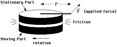
The experiment consists of a moving part which rotates against a stationary brass mass (containing a thermometer). These two parts exert frictional forces on each other which generate heat. The stationary mass is constrained from rotating only by a measured force F applied at a radius r from its center. This situation is shown in a schematic way below.

Figure 1
The moving part is rotated at a rate so that the frictional force transmitted to the stationary part just balances a constant torque applied to it and keeps it from moving. Under these conditions, all the work done to keep the moving part rotating is converted to heat by friction.
What is the rate at which mechanical energy is converted into heat? Well, it
does not matter which part moves and which is stationary (except for the
convenience of doing the experiment); the relative motion is what produces the
friction that balances the applied torque. So, imagine that the moving part
was stopped. The same balance would occur when the stationary part rotates
under the influence of the applied torque such that the relative motion is the
same as before; that is, at the same rate that the moving part was turning.
The rate at which work would be done by the applied force in this hypothetical
situation is F s, where s is the linear displacement parallel to
the direction of the force. In N revolutions the force effectively acts
over a distance s =
 ,
so that the work done, which is the rate at which mechanical energy is
converted into heat in both situations is,
 .
(4)
.
(4)
Thus by measuring the applied force F and the radius of the
point of application r , you can determine the frictional work done
W by counting the number of revolutions N. When F is
expressed in Newtons and r in meters then W is in Joules. This
heat is absorbed by the friction producing assembly and raises its temperature.
By measuring the resulting change in temperature
 T
with the thermometer, the heat absorbed by each of the parts is,
 ,
(5)
,
(5)
where
 is
the heat absorbed by the ith part with mass mi and
specific heat Ci, can be accounted for.
Now the thermometer itself consists of both mercury and glass, and these substances have different specific heats. However, by fortunate coincidence the product of density and specific heat is,
 ,
(6)
,
(6)
and is nearly the same for both glass and mercury. So, for the thermometer,
 , (7)
, (7)
where Vt is the effective volume of the thermometer. Since glass is a poor conductor of heat and the mercury column is very fine, there will not be much heat conducted up the thermometer during the experiment. Consequently, Vt amounts to only that portion of the volume of the thermometer in direct thermal contact with the heat producing assembly.
The total heat absorbed can then be obtained by adding together the partial heats,
 .
(8)
.
(8)
To do this the parts must be weighed and their specific heats known and
the effective thermometer volume must be measured. Then, from these results,
Joule's constant, J =
 ,
can be calculated to give the relationship between mechanical energy and heat.
There are two different kinds of apparatus (type A and B) in the lab which accomplish the same goals in slightly different ways. You only need to use one of the apparatus for the experiment.
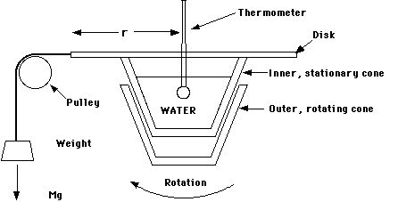
In apparatus A, the rubbing parts are a pair of brass cones. The outer, rotating cone is turned by an arrangement of pulleys and belts driven by a hand crank. The other cone rests inside it and is attached to a disk of radius r, from the perimeter of which a mass M is suspended over a pulley to apply a constant force, F = Mg.
In operation the hand-crank should be turned at a rate so that the frictional forces produced by the rotation of the outer cone exactly counter-balance the torque applied by the weight. That is, so that the inner cone and the attached weight remain stationary. When this is done, the work expended in turning the hand-crank is exactly that done by friction between the cones. A counter on the apparatus aids in the determination of N, the number of revolutions of the disk. The heat produced by friction is measured by determining the change in temperature of the brass cone assembly.
A drop of oil should be spread between the inner and outer cones for lubrication. Measure the temperature change at various time intervals with a thermometer immersed in water (to insure good thermal contact) in the inner brass cone. This water should be at room-temperature and fill the inner cone until it is about 3/4 full. Use alcohol thermometers for safety.
After assembly wait for the system to reach thermal equilibrium, note the depth
to which the thermometer is submerged and record the initial counter reading.
The assembly, which is heated up, consists of both cones, water, and the
thermometer, so the total heat generated
 is the sum of the partial heats absorbed by each of these parts,
 ,(9)
,(9)
where,
 ,
(10)
and the quantities;
mc = mass of both cones together (in grams),
mw = mass of water (in grams),
Vt = submerged volume of thermometer (in cm3); equivalent to grams of water.
The assembly must be measured after completing the experiment. To do so, disassemble the apparatus, being careful not to spill any water:
Putting everything together yields,
 ,
(11)

Figure 2: Apparatus Type A
where [[Delta]]T is the change in temperature during N revolutions of disc. You must also measure r the radius of disc. Note: If the string is NOT tangential to the perimeter of the disk, you must use the perpendicular distance of the line of the string from the center of the disk to get the moment arm, and use this instead of r.
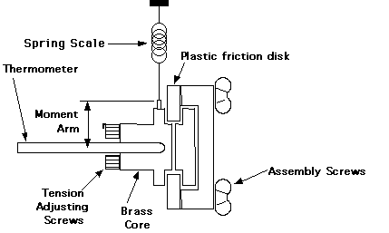
In Apparatus B, the rubbing parts are a plastic disk squeezed between a pair of brass cores. Tension screws can be adjusted to vary the amount of friction. The plastic disk is turned by a hand crank. A spring scale is attached by a wire to a winding screw on the periphery of one of the cores. This wire rides in a groove on the diameter of this core, to which it applies a measured force. In use, the plastic disk should be cranked at a rate so that the frictional forces exactly counter-balance the torque applied by the spring and the cores remain stationary.
The tension screws should be adjusted until the frictional load is around 1kg (+/-0.5kg) at a rate of one or two rotations per second; adjust them carefully and do not over-tighten them. After making these adjustments you should let the assembly cool to room temperature equilibrium before you do the experiment. To determine N, you must keep count the number of revolutions as you crank.
The heat produced by friction is measured by determining the change in temperature of the brass core assembly. This temperature change at several time intervals (every 50 rotations or so) is measured with a thermometer inserted in the core; it rests horizontally on a thermometer holder on the apparatus. Smear a small amount of grease on the thermometer bulb to insure good thermal contact with the brass core. The accuracy will decrease if you exceed about 10deg.C above ambient because then too much heat will leak to the surrounding air and the plastic friction disk.

Figure 3: Apparatus Type B
The items that are heated up consist of the brass core assembly (both
pieces of the core, the two tension screws and the wire mounting screw) and the
thermometer. The plastic disk has a very low thermal conductivity so the heat
it absorbs can be neglected. Then the total heat generated
 is,
is,
 ,
(12)
where
 and the quantities
mc = mass of brass core assembly (in grams),
Vt = volume of thermometer in core (in cm3)
must be measured after the experiment.
To do so, disassemble the apparatus by removing the assembly screws and the tension screws. Weigh all the brass pieces together. Note the depth to which the thermometer is inserted in the core. Weigh a small beaker containing some water. Insert the thermometer in the water to the depth you noted above and record the apparent increase in mass. Since water has a density of 1 gm/cm3, the increase in mass in grams is numerically equal to the submerged volume of the thermometer.
Putting everything together yields,
 ,
(13)
where [[Delta]]T is the change in temperature in N revolutions. You must also determine r the radius of core by measuring the diameter of the core with a pair of calipers.
You should note which kind of apparatus you will be using. The procedures are essentially the same but differ in the details appropriate to each kind of apparatus. Spend some time familiarizing yourself with your particular apparatus. You should practice coordinating between yourself and your lab partner the tasks of reading the thermometer at the right times, cranking at the proper speed, etc..
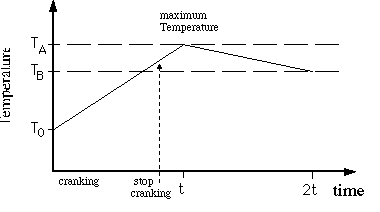
 is
the maximum temperature at time t (not necessarily exactly at the time
that you stop doing work), and
 is the temperature at time equals 2t. When plotting, draw two "best"
straight lines through the points for time
 and for time between t and 2t. The intersection determines the
time t when the temperature is at its maximum value (T=
 ).
See Figure 4.
The temperature change produced by doing work is apparently
 .
But during the time t heat was being lost to the environment by radiant
cooling. An estimate of this heat loss in time t is provided by the
temperature drop
 .
Thus
 is
not taken to be
 but,
but,
 .
(14)
 .
.

Figure 4