
Electromagnetic waves are produced by accelerating charges. The fields of the wave are self-supporting - the electric field induces the magnetic field, and the magnetic field induces the electric field. Both radio waves and light are electromagnetic waves; their main difference is their frequency. Radio waves are created by the acceleration of electrons in a radio antenna, and light waves are created by the oscillations of the electrons within atoms. The electromagnetic wave has two components: the electric radiation field and the magnetic radiation field.
The magnitude of the electric radiation field is directly proportional to the acceleration, and it is inversely proportional to the radial distance from the accelerating charge. In other words

where a(t) is the acceleration of the charge at time t, and c is the speed of propagation of the disturbance (speed of light).
Suppose we look at the electric field a long distance away from the accelerating charge. At this point the radial electric field, which falls of as 1/r2, can be neglected and only the transverse component of the field needs to be considered. We will assume that the charge accelerates during a short time interval and then continues to move with a constant velocity (see discussion in Chapter 35). If we want to study the variation of the transverse field over a limited range of distances, small compared to r, then the factor 1/r can be treated as a constant. The coordinate system that we will be using to study the propagation of the electromagnetic wave will have its x axis defined as the direction of propagation of the field. The y axis is taken to be parallel to the direction of the electric radiation field (see Figure 36.1). The electric radiation field produced by an accelerating charge will be non-zero only during a time interval [tau] which is the time interval during which the charge accelerates (see Chapter 35). These electromagnetic waves are called plane waves (although they are actually small patches of a spherical wave front). The propagating plane wave will change the electric field, which is initially zero, to a value Ey. This field will be exist during a time interval [tau] after which the transverse electric field returns to zero. The region is space in which the transverse field is non-zero and which propagates with the speed of light is also called a wave packet. The electric field of the wave packet can be written as

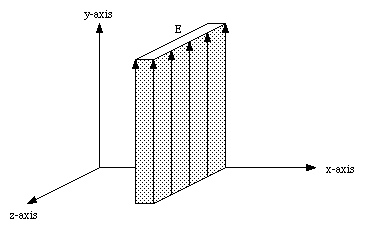

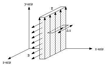
Consider a surface with width [Delta]x and length [Delta] z (see Figure 36.2). The width [Delta]x is chosen to be equal to the width of the wave packet ([Delta]x = c[tau]). The electric flux intercepted by the surface spanned by this path is zero before the wave packet arrives. During a time [Delta]t = [Delta]x / c the wave packet will sweep over the loop and fill the loop with electric flux. The maximum electric flux intercepted by this surface is equal to he product of the electric field Ey and the surface area ([Delta]x[Delta]z). The rate of change of electric flux is therefore equal to

The path integral of the magnetic field along the loop shown in Figure 36.2 is equal to


The induced magnetic field is time-dependent and will, in turn, induce an electric field. The induced electric field can be determined using Faraday's law of induction which relates the path integral of the induced electric field to the rate of change of magnetic flux

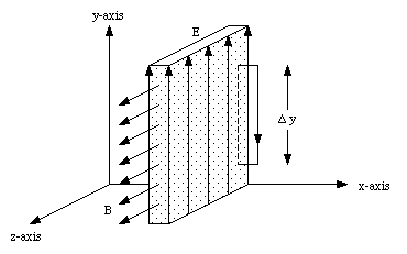
Consider the loop shown in Figure 36.3 with a width [Delta]x and a height [Delta]y, where [Delta]x is taken to be the width of the wave packet. The magnetic flux intercepted by the surface spanned by this loop will go from zero (when the wave packet has no overlap with the loop) to its maximum value of Bz[Delta]x[Delta]y in a time interval [Delta]t = [Delta]x/c. The rate of change of magnetic flux is thus equal to

The minus sign in this equation is a result of the direction of the path indicated (using the right-hand rule you can show that the magnetic field lines along the negative z-axis make a positive contribution to the intercepted flux, while field lines along the positive z-axis make a negative contribution to the intercepted flux). The path integral of the electric field along the path indicated in Figure 36.3 at a time when one edge of the loop is inside the wave packet is equal to

Applying Faraday's law of induction we can determine the induced electric field Ey


or

Equation (36.12) is a theoretical expression for the speed of propagation of an electromagnetic wave in vacuum, and shows that the electromagnetic waves propagate with the speed of light (which is just one type of electromagnetic radiation).
a) One type of antenna for a radio receiver consists of a short piece of straight wire; when the electric field of the radio wave strikes this wire it makes currents flow along it, which are detected an amplified by a receiver. Suppose the electric field of the radio wave is vertical. What must be the orientation of the wire for maximum sensitivity ?
b) Another type of antenna consists of a circular loop; when the magnetic field of the radio wave strikes this loop it induces currents around it. Suppose that the magnetic field of a radio wave is horizontal. What must be the orientation of the loop for maximum sensitivity ?
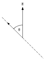

Equation (36.13) shows that the magnitude of the electric field along the antenna, and therefore the magnitude of the induced current, will be maximum when [theta] = 0deg..
b) A changing magnetic field will induce an emf in a conducting loop (Faraday's law of induction). The induced emf is proportional to the magnetic flux intercepted by the surface spanned by the loop. In order to maximize the induced current, we have to maximize the induced emf, and therefore maximize the magnetic flux intercepted by the loop. This can be achieved of the loop is located perpendicular to the direction of the magnetic field.
Although the relation between the electric and magnetic field strength shown in eq.(36.10) was obtained for a wave packet consisting of a region of constant electric field, the results are of general validity because an arbitrary wave can be regarded as a succession of short wave packets with piece wise constant electric fields. Equation (36.10) is therefore valid in general. Other general features of electromagnetic waves are:
1. the electric field is perpendicular to the direction of propagation
2. the magnetic field is perpendicular to both the electric field and the direction of propagation.
The direction of E and B are related by the right-hand rule; if the fingers are curled from E to B, then the thumb lies along the direction of propagation.
Most radiation fields are generated by charges moving with simple harmonic motion. In this case the acceleration of the charge will be a harmonic function of time:

where [omega] is the angular frequency of the motion. The electric field along the x axis is directed along the y axis and is equal to

The magnetic field will be directed along the z axis and has a magnitude equal to

Electromagnetic waves described by eq.(36.15) and eq.(36.16) are called plane harmonic waves. The waves described by eq.(36.15) and eq.(36.16) are waves traveling in the positive x direction. The electric and magnetic fields of a plane wave traveling in the negative x direction are given by the following equations


The minus sign in eq. (36.18) is required to make the direction of E and B consistent with the direction of propagation. The direction of the electric field of a electromagnetic wave is called the polarization of the wave.
An electromagnetic wave traveling along the x axis consists of the following superposition of two waves polarized along the y and z directions, respectively:

This electromagnetic wave is said to be circularly polarized.
a) Show that the magnitude of the electric field is E0 at all points of space and at all times.
b) Consider the point x = y = z = 0. What is the angle between E and the z axis at time t = 0 ? At time t = [pi] /2[omega] ? At time t = [pi] /[omega] ? At time t = 3[pi] /2[omega] ? Draw a diagram showing the x and y axes and the direction of E at these times. In a few words, describe the behavior of E as function of time.
a) The magnitude of the electric field can be obtained from its components along the y and z axes:

b) At time t = 0 the electric field is equal to

At time t = [pi] /2[omega] :

At time t = [pi] /[omega] :

At time t = 3 [pi] /2[omega] :

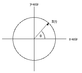
The electric field of the circularly polarized wave is constant in magnitude, but its direction is time dependent (see Figure 36.5):

An electromagnetic wave has the form

a) What is the direction of propagation of the wave ?
b) What is the direction of polarization of the wave, that is, what angle does the direction of the polarization make with the x, y, and z axes ?
c) Write down a formula for the magnetic field of this wave as function of space and time.
a) Equation (36.26) can be rewritten as

Comparing eq.(36.27) with eq.(36.17) we conclude that eq.(36.27) describes an electromagnetic wave traveling in the negative z direction.
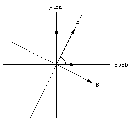
b) Since the electromagnetic wave travels along the z axis, the direction of polarization of the wave will be in the x-y plane (the direction of the electric field is always perpendicular to the direction of propagation). Eq.(36.27) shows that the direction of polarization of the electromagnetic wave is independent of time. The angle between the direction of polarization and the positive x axis is equal to (see Figure 36.6)

c) The magnitude of the magnetic field is equal to the magnitude of the electric field divided by the speed of light (see eq.(36.10)). The direction of the magnetic field is perpendicular to both the electric field and the direction of propagation. Since the direction of propagation is along the z axis, the direction of the magnetic field will be in the x-y plane. If the negative z axis is going in to the paper, then the right-hand rule requires that the magnetic field is pointing in the direction indicated in Figure 36.6. The magnetic field is thus given by

The electric field of a plane harmonic wave is position and time dependent. For an electromagnetic wave propagating in the positive x direction the transverse electric field is equal to

At a fixed time t the electric field is a harmonic function of x. The wavelength [lambda] of the wave is the distance over which the electric field changes from its maximum value (E0) to its minimum value (- E0) and back to its maximum value (E0). The electric field has the same value at points separated by one wavelength. This requires that

or

This condition is true at all times t and all distances x if

or

The ratio [omega]/2[pi] is called the frequency of the wave. Using the frequency [nu] we can rewrite eq.(36.34) as

Radio waves and TV waves have wavelengths ranging from a few centimeters to 105 meter. Microwaves have wavelengths as short as a millimeter. These waves (radio, tv, and microwaves) can be generated by oscillating charges in an antenna. Waves with wavelengths less than a millimeter can not be generated by oscillating currents in an antenna. Instead, they are generated by electrons oscillating within molecules and atoms. This type of motion produces infrared, visible, and ultraviolet light, and X-rays. The corresponding wavelengths range from 10-3 m to 10-11 m (visible light has wavelengths between 7 x 10⁻⁷ and 4 x 10⁻⁷m). Protons and neutrons moving in a nucleus emit gamma rays which have a wavelength between 10-11 m and 10-16 m.
The electric and magnetic fields of an electromagnetic wave contain energy. As the wave moves along, so does this energy. Consider a wave packet with width [Delta]x moving in the positive x direction. The transverse electric field is directed along the positive y axis and the magnetic field is directed along the positive z axis. The energy density of the electric field, uE, is equal to

The energy density of the magnetic field, uB, is equal to

The energy stored in the wave packet is equal to the energy density times the volume, or

where A is the surface area of the wave packet under consideration. However, for an electromagnetic wave the magnitude of the magnetic field is equal to the magnitude of the electric field divided by the speed of light (see eq.(36.10)). Equation (36.38) can now be rewritten as

Using eq.(36.12) we can eliminate the dependence of eq.(36.39) on [epsilon]0:

or

If we consider a fixed volume (fixed in space, with width [Delta]x) then eq.(36.41) is the maximum energy stored in this volume and it occurs at a particular time at which the wave packet completely overlaps with this volume. During a time interval [Delta]t = [Delta]x/c the wave packet moves out of the volume and the energy stored in this volume will return to zero. The rate of flow of energy through this volume is thus equal to

The energy flux (per unit area) through the volume is given by

The flux of energy associated with an electromagnetic wave is often expressed in terms of the Poynting vector. The Poynting vector is a vector with a direction along the flow and a magnitude given by eq.(36.43). The Poynting vector is defined, in general, as

Although we have derived the energy flux of the electromagnetic wave for a wave packet, the results also apply for plane harmonic waves. If the angular frequency of the transmitter is [omega], then at a fixed distance, the electric and magnetic fields will oscillate in time with the same angular frequency


The energy flux can be obtained by substituting eq.(36.45) and eq.(36.46) in eq.(36.44)

The time-averaged energy flux is equal to

The beam of a powerful laser has a diameter of 0.2 cm and carries a power of 6 kW. What is the time-average Poynting vector of this beam ? What are the amplitudes of the electric and magnetic fields ?
The laser beam carries a power of 6 kW. The flux of energy in the beam is equal to the power delivered divided by the surface over which this power is delivered. Thus

The amplitude of the electric field can be obtained using eq.(36.48)

The amplitude of the magnetic field can be obtained by dividing the amplitude of the electric field by the speed of light

A steady current of 12 A flows in a copper wire of radius 0.13 cm.
a) What is the longitudinal electric field in the wire ?
b) What is the magnetic field at the surface of the wire ?
c) What is the magnitude of the radial Poynting vector at the surface of the wire ?
d) Consider a 1.0-m segment of this wire. According to the Poynting vector, what amount of power flows into this piece of wire from the surrounding space ?
e) Show that the power calculated in part (d) coincides with the power of the Joule heat developed in the 1.0-m segment of wire.
a) Consider a 1-m segment of the wire. The resistance of this segment is equal to

The voltage across this segment can be obtained using Ohm's law

The longitudinal electric field in this segment is thus equal to

b) The magnetic field at the surface of the wire can be obtained using Ampere's law

c) The Poynting vector will be perpendicular to both the electric field and the magnetic field. Using the right-hand rule it can be shown that the Poynting vector is pointing along the radial direction, towards the center of the wire. The magnitude of the Poynting vector is equal to

d) Since the Poynting vector is directed radially inwards, the power flowing into a 1-m long segment of the wire is just equal to the magnitude of the Poynting vector times the surface area of the 1-m long segment

e) The Joule heat developed in the 1-m long segment of the wire is equal to

which is equal to the power flowing into the wire, calculated in part d).
When an electromagnetic wave strikes a charged particle, it will exert a force on it. The forces acting on the charged particle are the electric force and the magnetic force. The electric force will be directed along the y axis and has a magnitude equal to

The electric force will therefore only change the y component of the velocity of the charge. The x component of the velocity will be effected by the magnetic field. The x component of the magnetic force is given by

Equation (36.60) can be rewritten in terms of the electric field Ey:

The electric field does work on the particle, and the rate of increase of its energy is given by

Comparing eq.(36.61) and (36.62) we conclude that

Equation (36.63) shows that the rate at which the particle acquires x momentum from the wave is proportional to the rate at which it acquires energy. Equation (36.64) can be rewritten as

If the wave loses all its energy and momentum to the particle then eq.(36.64) can be interpreted as stating that the change in the momentum of the charged particle is equal to

where U is the total energy of the wave. Since linear momentum is a conserved quantity, eq.(36.65) indicates that the wave initially carries a linear momentum equal to U/c. Equation (36.63) can be rewritten using eq.(36.42):

The momentum flow oscillates in the same way as the energy flow.
The change in the x component of the momentum per unit time is equal to the x component of the force exerted on the particle. Thus

Equation (36.67) can be expressed in terms of the Poynting vector

The force exerted by the wave per unit area is equal to

and is called the pressure of radiation. Note: this formula is only correct if the wave is completely absorbed. If the wave is totally reflected then the pressure of radiation is twice that given in eq.(36.69).
Astronauts of the future could travel all over the Solar System in a spaceship equipped with a large "sail" coated with a reflecting material. Such a "sail" would act as a mirror; the pressure of sunlight on this mirror could support and propel the spaceship. How large a "sail" do we need to support a spaceship of 70 metric tons (equal to the mass of Skylab) against the gravitational pull of the sun ? Ignore the mass of the "sail".
Suppose the area of the sail is A and that the spaceship is located at the same distance from the sun as the earth is. At this point the average energy flux in the sun light is equal to 1.4 . 10 3 W/m2. The force exerted by the reflected sun light is equal to

The gravitational force between the space ship and the sun is equal to

and this force is pointed in a direction opposite to that of the radiation force in eq.(36.70). These two equation can be used to determine that a sail of 4.4 x 10 7 m2 is needed to balance the attractive gravitational force with a repulsive radiation force.
If electromagnetic waves are emitted with a frequency [nu] from an emitter, than a receiver, at rest with respect to the emitter, will detect electromagnetic waves with the same frequency [nu]. If the emitter moves with respect to the source then the frequency received will not be the same as the frequency emitted. Suppose the emitter produces electromagnetic waves with frequency [nu]0. If the electromagnetic waves are detected by a receiver moving away from the emitter with a velocity v, than the frequency received by the receiver is equal to

If the received is approaching the emitter with a velocity v than the frequency received by the receiver is equal to

This shift in frequency is called the Doppler Shift.