
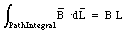
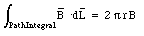
The magnetic field at a distance r from a very long straight wire, carrying a steady current I, has a magnitude equal to
and a direction perpendicular to r and I. The path integral along a circle centered around the wire (see Figure 31.1) is equal to
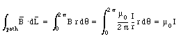
Here we have used the fact that the magnetic field is tangential at any point on the circular integration path.
This expression is Ampere's Law:
" The integral of B around any closed mathematical path equals u0 times the current intercepted by the area spanning the path "
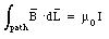
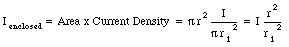
Six parallel aluminum wires of small, but finite, radius lie in the same plane. The wires are separated by equal distances d, and they carry equal currents I in the same direction. Find the magnetic field at the center of the first wire. Assume that the currents in each wire is uniformly distributed over its cross section.
A schematic layout of the problem is shown in Figure 31.3. The magnetic field generated by a single wire is equal to

where r is the distance from the center of the wire. Equation (31.5) is correct for all points outside the wire, and can therefore be used to determine the magnetic field generated by wire 2, 3, 4, 5, and 6. The field at the center of wire 1, due to the current flowing in wire 1, can be determined using Ampere's law, and is equal to zero. The total magnetic field at the center of wire 1 can be found by vector addition of the contributions of each of the six wires. Since the direction of each of these contributions is the same, the total magnetic field at the center of wire 1 is equal to
A solenoid is a device used to generate a homogeneous magnetic field. It can be made of a thin conducting wire wound in a tight helical coil of many turns. The magnetic field inside a solenoid can be determined by summing the magnetic fields generated by N individual rings (where N is the number of turns of the solenoid). We will limit our discussion of the magnetic field generated by a solenoid to that generated by an ideal solenoid which is infinitely long, and has very tightly wound coils.
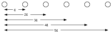
The ideal solenoid has translational and rotational symmetry. However, since magnetic field lines must form closed loops, the magnetic field can not be directed along a radial direction (otherwise field lines would be created or destroyed on the central axis of the solenoid). Therefore we conclude that the field lines in a solenoid must be parallel to the solenoid axis. The magnitude of the magnetic field can be obtained by applying Ampere's law.
where L is the horizontal length of the integration path. The current enclosed by the integration path is equal to N . I0 where N is the number of turns enclosed by the integration path and I0 is the current in each turn of the solenoid. Using Ampere's law we conclude that

or
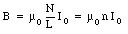
where n is the number of turns of the solenoid per unit length. Equation (31.9) shows that the magnetic field B is independent of the position inside the solenoid. We conclude that the magnetic field inside an ideal solenoid is uniform.
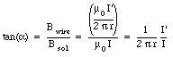
A long solenoid of n turns per unit length carries a current I, and a long straight wire lying along the axis of this solenoid carries a current I'. Find the net magnetic field within the solenoid, at a distance r from the axis. Describe the shape of the magnetic field lines.
The magnetic field generated by the solenoid is uniform, directed parallel to the solenoid axis, and has a magnitude equal to

The magnetic field if a long straight wire, carrying a current I' has a magnitude equal to

and is directed perpendicular to the direction of r and I'. The direction of Bwire is therefore perpendicular to the direction of Bsol. The net magnetic field inside the solenoid is equal to the vector sum of Bwire and Bsol. Its magnitude is equal to
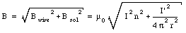
The angle a between the direction of the magnetic field and the z-axis is given by
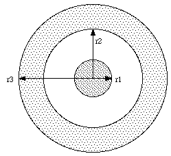
A coaxial cable consists of a long cylindrical copper wire of radius r1 surrounded by a cylindrical shell of inner radius r2 and outer radius r3 (see Figure 31.5). The wire and the shell carry equal and opposite currents I uniformly distributed over their volumes. Find formulas for the magnetic field in each of the regions r < r1, r1 < r < r2, r2 < r < r3, and r > r3.
The magnetic field lines are circles, centered on the symmetry axis of the coaxial cable. First consider an integration path with r < r1. The path integral of B along this path is equal to
The current enclosed by this integration path is equal to
Applying Faraday's law we can relate the current enclosed to the path integral of B
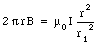
Therefore, the magnetic field is B is equal to


and the magnetic field is given by

In the third region (r2 < r < r3) the path integral of the magnetic field along a circular path with radius r is given by eq.(31.14). The enclosed current is equal to
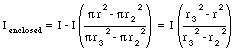
The magnetic field is therefore equal to
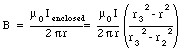
The current enclosed by an integration path with a radius r > r3 is equal to zero (since the current in the wire and in the shell are flowing in opposite directions). The magnetic field in this region is therefore also equal to zero.
The magnetic force acting on particle with charge q moving with velocity v is equal to

This force is always perpendicular to the direction of motion of the particle, and will therefore only change the direction of motion, and not the magnitude of the velocity. If the charged particle is moving in a uniform magnetic field, with strength B, that is perpendicular to the velocity v, then the magnitude of the magnetic force is given by

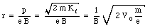
and its direction is perpendicular to v. As a result of this force, the particle will carry out uniform circular motion. The radius of the circle is determined by the requirement that the strength magnetic force is equal to the centripetal force. Thus
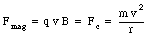
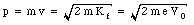
The radius r of the orbit is equal to

where p is the momentum of the charged particle. The distance traveled by the particle in one revolution is equal to
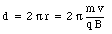
The time T required to complete one revolution is equal to

The frequency of this motion is equal to

and is called the cyclotron frequency. Equation (31.28) shows that the cyclotron frequency is independent of the energy of the particle, and depends only on its mass m and charge q.
The effect of a magnetic field on the motion of a charged particle can be used to determine some of its properties. One example is a measurement of the charge of the electron. An electron moving in a uniform magnetic field will described a circular motion with a radius given by eq.(31.25). Suppose the electron is accelerated by a potential V0. The final kinetic energy of the electron is given by

The momentum p of the electron is determined by its kinetic energy
The radius of curvature of the trajectory of the electron is thus equal to
Equation (31.31) shows that a measurement of r can be used to determine the mass over charge ratio of the electron.
Another application of the effect of a magnetic field on the motion of a charged particle is the cyclotron. A cyclotron consists of an evacuated cavity placed between the poles of a large electromagnet. The cavity is cut into two D-shaped pieces (called dees) with a gap between them. An oscillating high voltage is connected to the plates, generating an oscillating electric field in the region between the two dees. A charged particle, injected in the center of the cyclotron, will carry out a uniform circular motion for the first half of one turn. The frequency of the motion of the particle depends on its mass, its charge and the magnetic field strength. The frequency of the oscillator is chosen such that each time the particle crosses the gap between the dees, it will be accelerated by the electric field. As the energy of the ion increases, its radius of curvature will increase until it reaches the edge of the cyclotron and is extracted. During its motion in the cyclotron, the ion will cross the gap between the dees many times, and it will be accelerated to high energies.
Up to now we have assumed that the direction of the motion of the charged particle is perpendicular to the direction of the magnetic field. If this is the case, uniform circular motion will result. If the direction of motion of the ion is not perpendicular to the magnetic field, spiral motion will result. The velocity of the charged particle can be decomposed into two components: one parallel and one perpendicular to the magnetic field. The magnetic force acting on the particle will be determined by the component of its velocity perpendicular to the magnetic field. The projection of the motion of the particle on the x-y plane (assumed to be perpendicular to the magnetic field) will be circular. The magnetic field will not effect the component of the motion parallel to the field, and this component of the velocity will remain constant. The net result will be spiral motion.
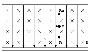
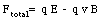
A charged particle moving in a region with an electric and magnetic field will experience a total force equal to

This force is called the Lorentz force.

The magnetic force acting on the charge particle is directed perpendicular to both v and B and has a magnitude equal to

The net force acting on the particle is the sum of these two components and has a magnitude equal to
If the charged particle has a velocity equal to

then the net force will be equal to zero, and the motion of the particle will be uniform linear motion. A device with crossed electric and magnetic fields is called a velocity selector. If slit are placed in the appropriate positions, it will transport only those particles that have a velocity defined by the magnitudes of the electric and magnetic fields.
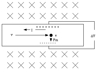
This effect is called the Hall effect.
The drift velocity of the electrons depend on the current I in the wire, its cross sectional area A and the density n of electrons (see Chapter 28):

Combining eq.(31.38) and eq.(31.37) we obtain the following expression for [Delta]V

A measurement of [Delta]V can therefore be used to determine n.
A current I flowing through a wire is equivalent to a collection of charges moving with a certain velocity vd along the wire. The amount of charge dq present in a segment dL of the wire is equal to

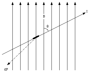
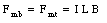
If the wire is placed in a magnetic field, a magnetic force will be exerted on each of the charge carriers, and as a result, a force will be exerted on the wire. Suppose the angle between the direction of the current and the direction of the field is equal to [theta] (see Figure 31.8). The magnetic force acting on the segment dL of the wire is equal to
The total force exerted by the magnetic field on the wire can be found by integrating eq.(31.41) along the entire wire.
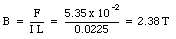
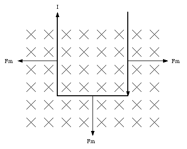
A balance can be used to measure the strength of the magnetic field. Consider a loop of wire, carrying a precisely known current, shown in Figure 31.9 which is partially immersed in the magnetic field. The force that the magnetic field exerts on the loop can be measured with the balance, and this permits the calculation of the strength of the magnetic field. Suppose that the short side of the loop measured 10.0 cm, the current in the wire is 0.225 A, and the magnetic force is 5.35 x 10⁻² N. What is the strength of the magnetic field ?
Consider the three segments of the current loop shown in Figure 31.9 which are immersed in the magnetic field. The magnetic force acting on segment 1 and 3 have equal magnitude, but are directed in an opposite direction, and therefore cancel. The magnitude of the magnetic force acting on segment 2 can be calculated using eq.(31.41) and is equal to
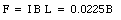
This force is measured using a balance and is equal to 5.35 x 10⁻² N. The strength of the magnetic field is thus equal to
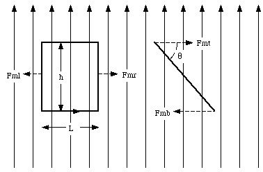
If a current loop is immersed in a magnetic field, the net magnetic force will be equal to zero. However, the torque on this loop will in general not be equal to zero. Suppose a rectangular current loop is placed in a uniform magnetic field (see Figure 31.10). The angle between the normal of the current loop and the magnetic field is equal to [theta]. The magnetic forces acting on the top and the bottom sections of the current loop are equal to
where L is the length of the top and bottom edge. The torque exerted on the current loop, with respect to its axis, is equal to
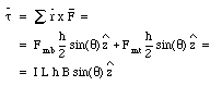

where

Using vector notation, eq.(31.45) can be rewritten as

where the direction of the magnetic moment is defined using the right-hand rule.
The work that must be done against the magnetic field to rotate the current loop by an angle d[theta] is equal to - [tau] d[theta]. The change in potential energy of the current loop when it rotates between [theta]0 and [theta]1 is given by
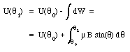
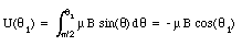
A common choice for the reference point is [theta]0 = 90deg. and U([theta]0) = 0 J. If this choice is made we can rewrite eq.(31.50) as
In vector notation:

The potential energy of the current loop has a minimum when u and B are parallel, and a maximum when u and B are anti-parallel.