
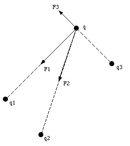
The presence of an electric charge produces a force on all other charges present. The electric force produces action-at-a-distance; the charged objects can influence each other without touching. Suppose two charges, q1 and q2, are initially at rest. Coulomb's law allows us to calculate the force exerted by charge q2 on charge q1 (see Figure 23.1). At a certain moment charge q2 is moved closer to charge q1. As a result we expect an increase of the force exerted by q2 on q1. However, this change can not occur instantaneous (no signal can propagate faster than the speed of light). The charges exert a force on one another by means of disturbances that they generate in the space surrounding them. These disturbances are called electric fields. Each electrically charged object generates an electric field which permeates the space around it, and exerts pushes or pulls whenever it comes in contact with other charged objects. The electric field E generated by a set of charges can be measured by putting a point charge q at a given position. The test charge will feel an electric force F. The electric field at the location of the point charge is defined as the force F divided by the charge q:


The definition of the electric field shows that the electric field is a vector field: the electric field at each point has a magnitude and a direction. The direction of the electric field is the direction in which a positive charge placed at that position will move. In this chapter the calculation of the electric field generated by various charge distributions will be discussed.
From the definition of the electric field it is clear that in order to calculate the field strength generated by a charge distribution we must be able to calculate the total electric force exerted on a test charge by this charge distribution.

A total amount of charge Q is uniformly distributed along a thin, straight, plastic rod of length L (see Figure 23.3).
a) Find the electric force acting on a point charge q located at point P, at a distance d from one end of the rod (see Figure 23.3).
b) Find the electric force acting on a point charge q located at point P', at a distance y from the midpoint of the rod (see Figure 23.3).
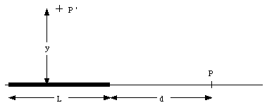
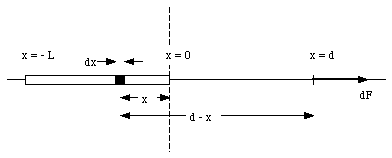
a) Figure 23.4 shows the force dF acting on point charge q, located at point P, as a result of the Coulomb interaction between charge q and a small segment of the rod. The force is directed along the x-axis and has a magnitude given by


b) Figure 23.5 shows the force acting on charge q, located at P', due to two charged segments of the rod. The net force dF exerted on q by the two segments of the rod is directed along the y-axis (vertical axis), and has a magnitude equal to

Note: the x-component of dFl cancels the x-component of dFr, and the net force acting on q is therefore equal to the sum of the y-components of dFl and dFr. The magnitude of dFl and dFr can be obtained from Coulomb's law:

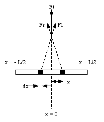

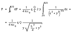
The net force acting on charge q can be obtained by summing over all segments of the rod.
Equation (23.1) shows that the electric field generated by a charge distribution is simply the force per unit positive charge. The procedure to measure the electric field, outlined in the introduction, assumes that all charges that generate the electric field remain fixed at their position while the test charge is introduced. To avoid disturbances to these charges, it is usually convenient to use a very small test charge.
A test charge placed a distance r from point charge Q will experience an electric force Fc given by Coulomb's law:

The electric field generated by the point charge Q can be calculated by substituting eq.(23.9) into eq.(23.1)

Suppose a very large sheet has a uniform charge density of [sigma] Coulomb per square meter. The charge sheet can be regarded as made up of a collection of many concentric rings, centered around the z-axis (which coincides with the location of the point of interest). The total electric field at this point can be obtained by vector addition of the electric field generated by all small segments of the sheet. Figure 23.6 shows the relevant dimension used to calculate the electric field generated by a ring with radius r and width dr. The strength of the electric field generated by each ring is directed along the z-axis and has a strength equal to

where dQ is the charge of the ring and z is the z-coordinate of the point of interest. The charge dQ can be expressed in terms of r, dr, and [sigma]

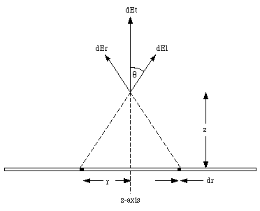

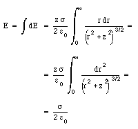
Substituting eq.(23.12) and eq.(23.13) into eq.(23.11) one obtains

The total electric field can be found by summing the contributions of all rings that make up the charge sheet
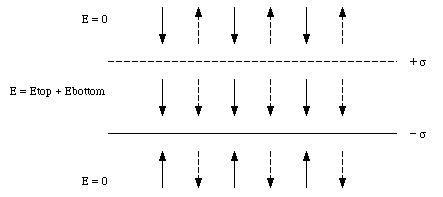

The electric fields above and below the plates have opposite directions (see Figure 23.7), and cancel. Therefore, two charged plates generate a homogeneous electric field confined to the region between the plates, and no electric field outside this region (note: this in contrast to a single charged sheet which produces an electric field everywhere).
Two large sheets of paper intersect each other at right angles. Each sheet carries a uniform distribution of positive charge of [sigma] C/m2. Find the magnitude of the electric field in each of the four quadrants.
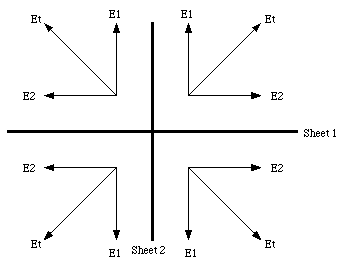

and its direction in each of the four quadrants is indicated in Figure 23.8.
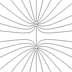
The electric field can be represented graphically by field lines. These lines are drawn in such a way that, at a given point, the tangent of the line has the direction of the electric field at that point. The density of lines is proportional to the magnitude of the electric field. Each field line starts on a positive point charge and ends on a negative point charge. Since the density of field lines is proportional to the strength of the electric field, the number of lines emerging from a positive charge must also be proportional to the charge. An example of field lines generated by a charge distributions is shown in Figure 23.9.
The net force acting on a neutral object placed in a uniform electric field is zero. However, the electric field can produce a net torque if the positive and negative charges are concentrated at different locations on the object. An example is shown in Figure 23.10. The figure shows a charge Q located on one end of a rod of length L and a charge - Q located on the opposite end of the rod. The forces acting on the two charges are given by

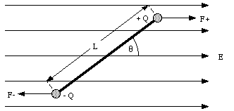

As a result of this torque the rod will rotate around its center. If [theta] = 0deg. (rod aligned with the field) the torque will be zero.
The distribution of the charge in a body can be characterized by a parameter called the dipole moment p. The dipole moment of the rod shown in Figure 23.10 is defined as

In general, the dipole moment is a vector which is directed from the negative charge towards the positive charge. Using the definition of the dipole moment from eq.(23.20) the torque of an object in an electric field is given by
