
The calculation of the magnetic field of a current distribution can, in principle, be carried out using Ampere's law which relates the path integral of the magnetic field around a closed path to the current intercepted by an arbitrary surface that spans this path:

Ampere's law is independent of the shape of the surface chosen as long as the current flows along a continuous, unbroken circuit. However, consider the case in which the current wire is broken and connected to a parallel-plate capacitor (see Figure 35.1). A current will flow through the wire during the charging process of the capacitor. This current will generate a magnetic field and if we are far away from the capacitor, this field should be very similar to the magnetic field produced by an infinitely long, continuous, wire. However, the current intercepted by an arbitrary surface now depends on the surface chosen. For example, the surface shown in Figure 35.1 does not intercept any current. Clearly, Ampere's law can not be applied in this case to find the magnetic field generated by the current.
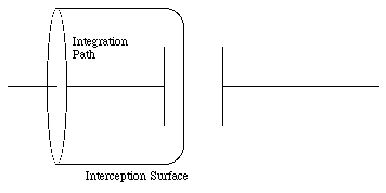

The electric field outside the capacitor is equal to zero. The electric flux, [Phi]E, intercepted by the surface shown in Figure 35.1 is equal to

If a current I is flowing through the wire, then the charge on the capacitor plates will be time dependent. The electric flux will therefore also be time dependent, and the rate of change of electric flux is equal to

The magnetic field around the wire can now be found by modifying Ampere's law

where [Phi]E is the electric flux through the surface indicated in Figure 35.1 In the most general case, the surface spanned by the integration path of the magnetic field can intercept current and electric flux. In such a case, the effects of the electric flux and the electric current must be combined, and Ampere's law becomes

The current I is the current intercepted by whatever surface is used in the calculation, and is not necessarily the same as the current in the wires. Equation (35.6) is frequently written as

where Id is called the displacement current and is defined as

A parallel-plate capacitor has circular plates of area A separated by a distance d. A thin straight wire of length d lies along the axis of the capacitor and connects the two plates. This wire has a resistance R. The exterior terminals of the plates are connected to a source of alternating emf with a voltage V = V0 sin([omega] t).
a) What is the current in the thin wire ?
b) What is the displacement current through the capacitor ?
c) What is the current arriving at the outside terminals of the capacitor ?
d) What is the magnetic field between the capacitor plates at a distance r from the axis ? Assume that r is less than the radius of the plates.
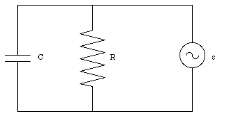
a) The setup can be regarded as a parallel circuit of a resistor with resistance R and a capacitor with capacitance C (see Figure 35.2). The current in the thin wire can be obtained using Ohm's law

b) The voltage across the capacitor is equal to the external emf. The electric field between the capacitor plates is therefore equal to

The electric flux through the capacitor is therefore equal to

The displacement current Id can be obtained by substituting eq.(35.11) into eq.(35.8)

The current at the outside terminals of the capacitor is the sum of the current used to charge the capacitor and the current through the resistor. The charge on the capacitor is equal to

The charging current is thus equal to

The total current is therefore equal to

d) The magnetic field lines inside the capacitor will form concentric circles, centered around the resistor (see Figure 35.3). The path integral of the magnetic field around a circle of radius r is equal to

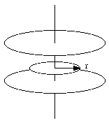

The displacement current intercepted by this surface is equal to

The current intercepted by the surface is equal to the current through the resistor (eq.(35.9)). Ampere's law thus requires
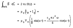
The strength of the magnetic field is thus equal to

The fundamental equations describing the behavior of electric and magnetic fields are known as the Maxwell equations. They are


Maxwell's equations provide a complete description of the interactions among charges, currents, electric fields, and magnetic fields. All the properties of the fields can be obtained by mathematical manipulations of these equations. If the distribution of charges and currents is given, than these equations uniquely determine the corresponding fields.
Prove that Maxwell's equations mathematically imply the conservation of electric charge; that is, prove that if no electric current flows into or out a given volume, then the electric charge within this volume remains constant.
Equation (35.21) shows that the enclosed charge Q is related to the electric flux [Phi]E:

The rate of change of the enclosed charge can be determined by differentiating eq.(35.25) with respect to time

The closed surface used in eq.(35.24) to determine the flux and current intercepted can be replaced by a bag whose mouth has shrunk to zero. The path integral of the magnetic field along the mouth is therefore equal to zero, and eq.(35.24) can be written as

Using eq.(35.26) we can rewrite eq.(35.27) as

In other words, if no current flows in or out of the enclosed volume (I = 0) then the electric charge within this volume will remain constant. This implies conservation of charge.
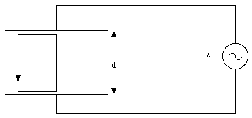
The electric field between the plates of a parallel-plate capacitor is determined by the external emf. If the distance between the plates is d (see Figure 35.4) then the electric field between the plates is equal to

This time-dependent electric field will induce a magnetic field with a strength that can be obtained via Ampere's law. Consider a circular Amperian loop of radius r. The path integral of the magnetic field around this loop is equal to

The electric flux though the surface spanned by this path is equal to


Using Ampere's law we obtain for the magnetic field

This time-dependent magnetic field will induce an electric field. The total electric field inside the capacitor will therefore be the sum of the constant electric field generated by the source of emf and the induced electric field, generated by the time-dependent magnetic field. The strength of the induced electric field can be calculated using Faraday's law of induction. Consider the closed path indicated in Figure 35.4. We take the induced electric field on the capacitor axis equal to zero. The path integral of the induced electric field along the path indicated is then equal to

where Eind is reckoned to be positive if it is directed upwards. The magnetic flux through the surface spanned by the loop indicated in Figure 35.4 is equal to
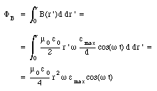
Thus

The induced electric field, Eind, can be obtained from Faraday's law of induction (eq.(35.23)) and is equal to

The total electric field is therefore equal to

But the addition of the induced field implies that a correction needs to be made to the magnetic field calculated before (eq.(35.33)). This in turn will modify the induced current and this process will go on forever. If we neglect the additional corrections, then eq.(35.38) shows that the electric field vanishes at a radius R if

or

If we create a cavity by enclosing the capacitor with a conducting cylinder of radius R then eq.(35.40) can be used to determine the frequency of the driving emf that will produce a standing wave. This frequency is called the resonance frequency and it is equal to

For a cavity with R = 0.5 m the resonance frequency is 1.2 GHz. Electromagnetic radiation with a frequency in this range is called microwave radiation, and the cavity is called a microwave oven.
The electric field produced by a stationary charge is stationary. When the charge accelerates, it produces extra electric and magnetic fields that travel outward from the position of the charge. These radiation fields are called electromagnetic waves. They travel with the speed of light (in vacuum) and carry energy and momentum away from the charge. Their properties are determined by the properties of the accelerated charge, and in this manner provide a means to transmit information at the speed of light over long distances.
Consider a charge q initially at rest (for t < 0). Between t = 0 and t = [tau], the charge accelerates with an acceleration a. After t = [tau] the charge moves with a constant velocity (v = a[tau]). We will assume that the final velocity of the charge is small compared to the speed of light (v << c) and that the time period [tau] during which the charge accelerates is short. The electric field generated by the charge at a time t > [tau] consists of three separate regions (see Figure 35.5). In the region r > ct the field lines will be that of a point charge at rest at the origin (electromagnetic waves travel with the speed of light, and the region with r > ct can not know yet that the charge has moved away from the origin). In the spherical region with radius r < c(t - [tau]), centered at x = vt, the electric field will that of a uniformly moving charge. The disturbance produced by the accelerated charge is confined to the region between these two spheres and the effect of the acceleration is a kink in the field lines. The electric field in this region has two components: a radial component and a transverse component.
The radial component is determined by Gauss' law. Consider a spherical Gaussian surface located between the two spheres shown in Figure 35.5. The charge enclosed by this surface is equal to q. The electric flux through this surface depends only on the radial component of the field. Applying Gauss' law we conclude that the radial component of the electric field is simply the usual Coulomb field

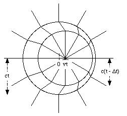

Since the radial field is known, eq.(35.42), we can use eq.(35.43) to determine the transverse component of the electric field:

The distance r at which the kink occurs is related to the time t at which we look at the field:

Eliminating the dependence on t in eq.(35.44) we obtain the following expression for the transverse component of the electric field:

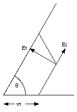
The equation for the transverse electric field (eq.(35.46)) is valid in general, even if the acceleration is not constant. If the charge oscillates back and forth with a simple harmonic motion of frequency [omega], then the acceleration at time t will be equal to

In order to determine the radiation field at a time t and a distance r, we have to realize that the acceleration a used in eq.(35.46) should be the acceleration at time t - r/c, where r/c is the time required for a signal to travel over a distance r. The radiation field for the oscillating charge is therefore equal to

On a radio antenna (a straight piece of wire), electrons move back and forth in unison. Suppose that the velocity of the electrons is v = v0 cos([omega] t), where v0 = 8.0 x 10 -3 m/s and [omega] = 6.0 x 10 6 rad/s.
a) What is the maximum acceleration of the electrons ?
b) Corresponding to this maximum acceleration, what is the strength of the transverse electric field produced by one electron at a distance of 1.0 km fro the antenna in a direction perpendicular to the antenna ? What is the time delay (or retardation) between the instant of maximum acceleration and the instant at which the corresponding electric field reaches a distance of 1.0 km ?
c) There are 2.0 x 10 24 electrons on the antenna. What is the collective electric field produced by all electrons acting together ? Assume the antenna is sufficiently small so that all electrons contribute just about the same electric field at a distance of 1.0 km.
a) The acceleration of the electrons can be obtained by differentiating their velocity with respect to time:

The maximum acceleration is thus equal to

b) The maximum transverse electric field at a distance of 1.0 km (= 1000 m), in a direction perpendicular to the antenna ([theta] = 90deg.), can be obtained using eq.(35.48):

Since the propagation speed of the radiation field is equal to the speed of light, c, the maxima in the radiation field will occur a time period [Delta]t after the maxima in the acceleration of the electron. The length of this period, [Delta]t, is equal to

c) Assuming that all the electrons are in phase, then the maximum total transverse electric field at a distance of 1.0 km is equal to the number of electrons times the maximum transverse electric field produced by a single electron. Thus

When a charge accelerates from rest it will produce a magnetic field. Initially, the magnetic field will be equal to zero (charge at rest). As a result of the acceleration a disturbance will move outward and change the magnetic field from its initial value (B = 0 T) to its final value, in much the same way as we observed for the electric field. The magnetic field can be obtained from the electric flux via the Maxwell-Ampere law which states that

Note that the current I does not appear in eq. (35.54). Since we are looking in the region away from the moving charge, the current intercepted by a surface spanned by the path used to evaluate the path integral of B is equal to zero. The induced magnetic field will be time-dependent and, therefore, will induce an electric field via Faraday's law. This induced electric field will again be time dependent and induce another magnetic field, and this process continues. The combined electric and magnetic radiation fields produced by the accelerating charge are called electromagnetic waves. They are self-supporting; the electric field induces a magnetic field, and the induced magnetic field induces an electric field. Because the electric and magnetic fields naturally support each other, the electromagnetic wave does not require a medium for its propagation, and it readily propagates in vacuum. The Maxwell equations can be used to show that the product of u0 and [epsilon]0 is equal to 1/c2. Or,

This equation was one of the great and early triumphs of Maxwell's electromagnetic theory of light. It shows that electricity and magnetism are two different aspects of the same phenomena.