

where u0 is called the permeability constant which is equal to 4[pi] x 10-7 Ns2/C2, and r is the distance between the two charges (see Figure 30.1). The ratio R of the magnetic force and the electric force is equal to

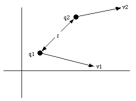

where c is the velocity of light in vacuum (c = 3 x 10⁸ m/s). Clearly, the magnetic force is small compared with the electric force unless the speed of the particles is high (a significant fraction of the velocity of light).
A magnetic field B can be associated with the magnetic force. The magnetic field at some point in the vicinity of a moving charge can be determined by placing a test charge at that point and moving it with some velocity v. The test charge will experience, besides the electric force, a magnetic force Fmag. Per definition, the magnetic field B is related to the magnetic force Fmag via

A measurement of the magnetic force acting on the test charge for various directions of v can be used to determine the magnetic field B. The magnetic force is always perpendicular to the velocity vector and the direction of the magnetic field. The unit of magnetic field strength is the Tesla (T). Comparing eq.(30.1) and eq.(30.4) we can determine the magnetic field generated by a point charge q2 moving with a velocity v2:

Similar to electric field lines we can graphically represent the magnetic field by field lines. The density of field lines indicates the strength of the magnetic field. The tangent of the field lines indicates the direction of the magnetic field. The magnetic field lines form closed loops, that is they do not begin or end anywhere in the way that the electric field lines begin and end on positive and negative charges. This immediately implies that the magnetic flux through an arbitrary closed surface is equal to zero:

The principle of superposition is also valid for the magnetic field.
At the surface of a pulsar, or neutron star, the magnetic field may be as strong as 108 T. Consider the electron in a hydrogen atom on the surface of the neutron star. The electron is at a distance of 0.53 x 10⁻¹⁰ m from the proton and has a speed of 2.2 x 10⁶ m/s. Compare the electric force that the proton exerts on the electron with the magnetic force that the magnetic field of the neutron star exerts on the electron. Is it reasonable to expect that the hydrogen atom will be strongly deformed by the magnetic field ?
The electron in a hydrogen atom is at a distance r equal to 0.53 x 10⁻¹⁰ m from the proton. The electric force acting on the electron is equal to

The maximum magnetic force acting on the electron occurs when the direction of the electron is perpendicular to the direction of the magnetic field. The maximum magnetic force is equal to

Comparing eq.(30.7) and eq.(30.8) we conclude that the magnetic field is significantly stronger hat the electric field, and we expect that the orbits of the electrons are strongly affected by the intense magnetic field.
The definition of the magnetic force showed that two moving charges experience a magnetic force. In other words, a moving charge produces a magnetic field which results in a magnetic force acting on all charges moving in this field.
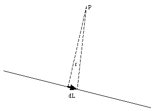
A current flowing through a wire is equivalent to a collection of electrons moving with a certain velocity along the direction of the wire. Each of the moving electrons produces a magnetic field that is given by eq.(30.5). Consider a small segment of the wire with a length dL (see Figure 30.2). At any given time, a charge dq will be located in this segment. The magnetic field, dB, generated by this charge at point P is equal to

where v is the velocity of the charge carriers. The time dt that it takes for all original charge carriers to leave the segment dL is given by

The current I in the wire can now be obtained easily


and substituted into eq.(30.9):

Equation (30.13) is called the Biot-Savart Law.
Helmholtz coils are often used to make reasonably uniform magnetic fields in laboratories. These coils consist of two thin circular rings of wire parallel to each other and on a common axis, the z-axis. The rings have a radius R and they are separated by a distance which is also R. These rings carry equal currents in the same direction. Find the magnetic field at any point on the z-axis.
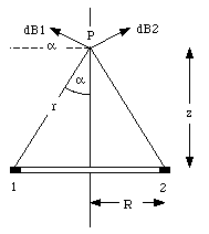

To obtain eq.(30.14) we have used the fact that for any point on the ring, the position vector r is perpendicular to the direction of dL. The z-component of the magnetic field dB is equal to

The magnitude of the position vector r is related to R and z:

The angle a is also related to R and z:

Combining eqs.(30.15), (30.16) and (30.17) we obtain

Integrating eq.(30.18) over the whole ring we obtain for the total field generated by the ring

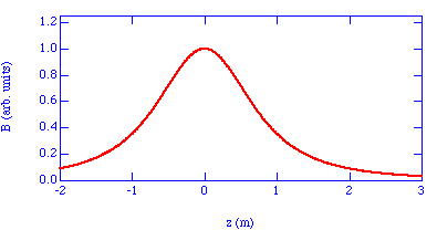
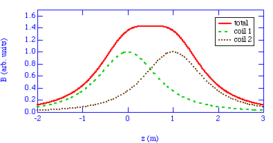
Figure 30.4 shows the magnetic field generated by one coil with a radius of 1 m, located at z = 0 m.
To find the field generated by a pair of Helmholtz coils, we assume that the coils are centered at z = 0 and at z = R. The magnetic field generated by the coil located at z = 0 is given by eq.(30.19). The magnetic field generated by the coil located at z = R is given by

The total field on the axis of a pair of Helmholtz coils is equal to the sum of the field generated by coil 1 and the field generated by coil 2:

The total magnetic field generated by a pair of Helmholtz coils is shown in Figure 30.5 where also the contributions of the two coils are shown individually. We observe that the field is very homogeneous between the coils (0 < z < R).
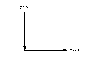
A very long wire is bent at a right angle near its midpoint. One branch of it lies along the positive x-axis and the other along the positive y-axis (see Figure 30.6). The wire carries a current I. What is the magnetic field at a point in the first quadrant of the x-y plane ?
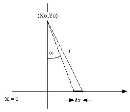

The position x of the segment under consideration is determined by the angle a:

or

From eq.(30.24) we can obtain a relation between dx and da:

Furthermore,

Substituting eq.(30.25) and eq.(30.26) into eq(30.22) we obtain
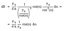
The total field can be obtained by integrating eq.(30.27) over the wire. The integration limits are

and

The result of the integration is

The field of the vertical wire can be obtained in a similar fashion:

The magnitude of the total field is thus equal to

The magnetic field on the axis of a current loop was discussed in Problem 30.33. At large distances from the current loop (z >> R) the field is approximately equal to

which shows that the magnetic field strength decreases as 1/z3. This dependence of the magnetic field strength on distance is similar to the dependence observed for the electric field strength of an electric dipole:

Equation (30.33) is often rewritten as

where

is called the magnetic dipole moment of the loop. In general, the dipole moment of a current loop is equal to

Magnetic dipole moments exist for objects as small as electrons and as large as the earth.
An amount of charge Q is uniformly distributed over a disk of paper of radius R. The disk spins about its axis with angular velocity [omega]. Find the magnetic dipole moment of the disk.
The first step to solve this problem is to determine the dipole moment of a ring of the disk, with radius r and with a width dr. The amount of charge dq on this ring is equal to

The angular velocity of the disk is [omega] and its period T is equal to

During one period the charge dq will pass any given point on the ring. The current dI is thus equal to

The magnetic dipole moment du of the ring is equal to

The total dipole moment of the disk can be found by integrating eq.(30.41) between r = 0 and r = R:
