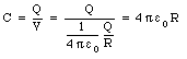
A capacitor is an arrangement of conductors that is used to store electric charge. A very simple capacitor is an isolated metallic sphere. The potential of a sphere with radius R and charge Q is equal to
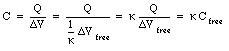
Equation (27.1) shows that the potential of the sphere is proportional to the charge Q on the conductor. This is true in general for any configuration of conductors. This relationship can be written as

where C is called the capacitance of the system of conductors. The unit of capacitance is the farad (F). The capacitance of the metallic sphere is equal to
Another example of a capacitor is a system consisting of two parallel metallic plates. In Chapter 26 it was shown that the potential difference between two plates of area A, separation distance d, and with charges +Q and -Q, is given by

Using the definition of the capacitance (eq.(27.2)), the capacitance of this system can be calculated:

Equation (27.2) shows that the charge on a capacitor is proportional to the capacitance C and to the potential V. To increase the amount of charge stored on a capacitor while keeping the potential (voltage) fixed, the capacitance of the capacitor will need to be increased. Since the capacitance of the parallel plate capacitor is proportional to the plate area A and inversely proportional to the distance d between the plates, this can be achieved by increasing the surface area A and/or decreasing the separation distance d. These large capacitors are usually made of two parallel sheets of aluminized foil, a few inches wide and several meters long. The sheets are placed very close together, but kept from touching by a thin sheet of plastic sandwiched between them. The entire sandwich is covered with another sheet of plastic and rolled up like a roll of toilet paper.
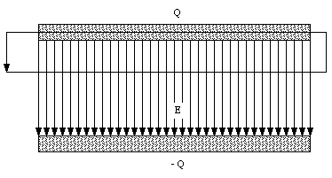
The tube of a Geiger counter consists of a thin straight wire surrounded by a coaxial conducting shell. The diameter of the wire is 0.0025 cm and that of the shell is 2.5 cm. The length of the tube is 10 cm. What is the capacitance of a Geiger-counter tube ?
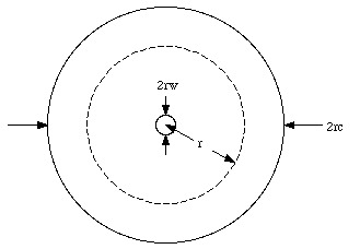
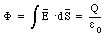
The problem will be solved under the assumption that the electric field generated is that of an infinitely long line of charge. A schematic side view of the tube is shown in Figure 27.1. The radius of the wire is rw, the radius of the cylinder is rc, the length of the counter is L, and the charge on the wire is +Q. The electric field in the region between the wire and the cylinder can be calculated using Gauss' law. The electric field in this region will have a radial direction and its magnitude will depend only on the radial distance r. Consider the cylinder with length L and radius r shown in Figure 27.1. The electric flux [Phi] through the surface of this cylinder is equal to

According to Gauss' law, the flux [Phi] is equal to the enclosed charge divided by [epsilon]0. Therefore
The electric field E(r) can be obtained using eq.(27.7):

The potential difference between the wire and the cylinder can be obtained by integrating the electric field E(r):
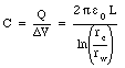
Using eq.(27.2) the capacitance of the Geiger tube can be calculated:
Substituting the values for rw, rc, and L into eq.(27.10) we obtain

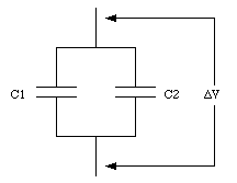
The symbol of a capacitor is shown in Figure 27.2. Capacitors can be connected together; they can be connected in series or in parallel. Figure 27.3 shows two capacitors, with capacitance C1 and C2, connected in parallel. The potential difference across both capacitors must be equal and therefore
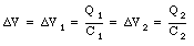

Using eq.(27.12) the total charge on both capacitors can be calculated

Equation (27.13) shows that the total charge on the capacitor system shown in Figure 27.3 is proportional to the potential difference across the system. The two capacitors in Figure 27.3 can be treated as one capacitor with a capacitance C where C is related to C1 and C2 in the following manner

Figure 27.4 shows two capacitors, with capacitance C1 and C2, connected in series. Suppose the potential difference across C1 is [Delta]V1 and the potential difference across C2 is [Delta]V2. A charge Q on the top plate will induce a charge -Q on the bottom plate of C1. Since electric charge is conserved, the charge on the top plate of C2 must be equal to Q. Thus the charge on the bottom plate of C2 is equal to -Q. The voltage difference across C1 is given by

and the voltage difference across C2 is equal to

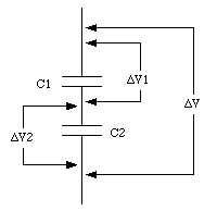
Equation (27.17) again shows that the voltage across the two capacitors, connected in series, is proportional to the charge Q. The system acts like a single capacitor C whose capacitance can be obtained from the following formula

A multi-plate capacitor, such as used in radios, consists of four parallel plates arranged one above the other as shown in Figure 27.5. The area of each plate is A, and the distance between adjacent plates is d. What is the capacitance of this arrangement ?
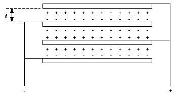
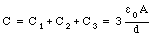
The multiple capacitor shown in Figure 27.5 is equivalent to three identical capacitors connected in parallel (see Figure 27.6). The capacitance of each of the three capacitors is equal and given by

The total capacitance of the multi-plate capacitor can be calculated using eq.(27.14):
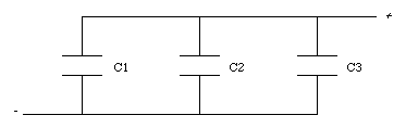
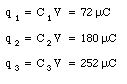
Three capacitors, of capacitance C1 = 2.0 uF, C2 = 5.0 uF, and C3 = 7.0 uF, are initially charged to 36 V by connecting each, for a few instants, to a 36-V battery. The battery is then removed and the charged capacitors are connected in a closed series circuit, with the positive and negative terminals joined as shown in Figure 27.7. What will be the final charge on each capacitor ? What will be the voltage across the points PP' ?
The initial charges on each of the three capacitors, q1, q2, and q3, are equal to
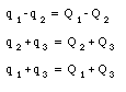
After the three capacitors are connected, the charge will redistribute itself. The charges on the three capacitors after the system settles down are equal to Q1, Q2, and Q3. Since charge is a conserved quantity, there is a relation between q1, q2, and q3, and Q1, Q2, and Q3:
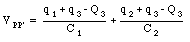
The voltage between P and P' can be expressed in terms of C3 and Q3, or in terms of C1, C2, Q1, and Q2:

and

Using eq.(27.22) the following expressions for Q1 and Q2 can be obtained:


Substituting eq.(27.25) and eq.(27.26) into eq.(27.24) we obtain
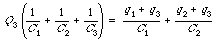
Combining eq.(27.27) and eq.(27.23), Q3 can be expressed in terms of known variables:
Substituting the known values of the capacitance and initial charges we obtain

The voltage across P and P' can be found by combining eq.(27.29) and eq.(27.23):
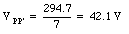
The charges on capacitor 1 and capacitor 2 are equal to


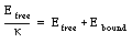
If the space between the plates of a capacitor is filled with an insulator, the capacitance of the capacitor will chance compared to the situation in which there is vacuum between the plates. The change in the capacitance is caused by a change in the electric field between the plates. The electric field between the capacitor plates will induce dipole moments in the material between the plates. These induced dipole moments will reduce the electric field in the region between the plates. A material in which the induced dipole moment is linearly proportional to the applied electric field is called a linear dielectric. In this type of materials the total electric field between the capacitor plates E is related to the electric field Efree that would exist if no dielectric was present:

where [kappa] is called the dielectric constant. Since the final electric field E can never exceed the free electric field Efree, the dielectric constant [kappa] must be larger than 1.
The potential difference across a capacitor is proportional to the electric field between the plates. Since the presence of a dielectric reduces the strength of the electric field, it will also reduce the potential difference between the capacitor plates (if the total charge on the plates is kept constant):

The capacitance C of a system with a dielectric is inversely proportional to the potential difference between the plates, and is related to the capacitance Cfree of a capacitor with no dielectric in the following manner
Since [kappa] is larger than 1, the capacitance of a capacitor can be significantly increased by filling the space between the capacitor plates with a dielectric with a large [kappa].
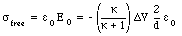
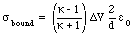
The electric field between the two capacitor plates is the vector sum of the fields generated by the charges on the capacitor and the field generated by the surface charges on the surface of the dielectric. The electric field generated by the charges on the capacitor plates (charge density of [sigma]free) is given by

Assuming a charge density on the surface of the dielectric equal to [sigma]bound, the field generated by these bound charges is equal to

The electric field between the plates is equal to Efree/[kappa] and thus
Substituting eq.(27.36) and eq.(27.37) into eq.(27.38) gives
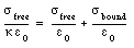
or

A parallel plate capacitor of plate area A and separation distance d contains a slab of dielectric of thickness d/2 (see Figure 27.8) and dielectric constant [kappa]. The potential difference between the plates is [Delta]V.
a) In terms of the given quantities, find the electric field in the empty region of space between the plates.
b) Find the electric field inside the dielectric.
c) Find the density of bound charges on the surface of the dielectric.
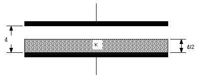
a) Suppose the electric field in the capacitor without the dielectric is equal to E0. The electric field in the dielectric, Ed, is related to the free electric field via the dielectric constant [kappa]:

The potential difference between the plates can be obtained by integrating the electric field between the plates:
The electric field in the empty region is thus equal to
b) The electric field in the dielectric can be found by combining eq.(27.41) and (27.43):
c) The free charge density [sigma]free is equal to
The bound charge density is related to the free charge density via the following relation

Combining eq.(27.45) and eq.(27.46) we obtain
The electric field in an "empty" capacitor can be obtained using Gauss' law. Consider an ideal capacitor (with no fringing fields) and the integration volume shown in Figure 27.9. The area of each capacitor plate is A and the charges on the plates are +/-Q. The charge enclosed by the integration volume shown in Figure 27.9 is equal to +Q. Gauss' law states that the electric flux [Phi] through the surface of the integration volume is related to the enclosed charge:
If a dielectric is inserted between the plates, the electric field between the plates will change (even though the charge on the plates is kept constant). Obviously, Gauss' law, as stated in eq.(27.48), does not hold in this case. The electric field E between the capacitor plates is related to the dielectric-free field Efree:

where [kappa] is the dielectric constant of the material between the plates. Gauss' law can now be rewritten as
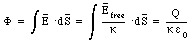
Gauss' law in vacuum is a special case of eq.(27.50) with [kappa] = 1.
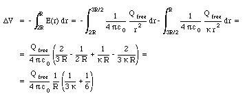
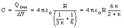
A metallic sphere of radius R is surrounded by a concentric dielectric shell of inner radius R, and outer radius 3R/2. This is surrounded by a concentric, thin, metallic shell of radius 2R (see Figure 27.10). The dielectric constant of the shell is [kappa]. What is the capacitance of this contraption ?
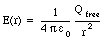
Suppose the charge on the inner sphere is Qfree. The electric field inside the dielectric can be determined by applying Gauss' law for a dielectric (eq.(27.50)) and using as the integration volume a sphere of radius r (where R < r < 3R/2)
The electric field in this region is therefore given by
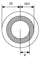
Using the electric field from eq.(27.52) and eq.(27.53) we can determine the potential difference [Delta]V between the inner and outer sphere:
The capacitance of the system can be obtained from eq.(27.54) using the definition of the capacitance in terms of the charge Q and the potential difference [Delta]V:
The electric potential energy of a capacitor containing no dielectric and with charge +/-Q on its plates is given by
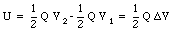
where V1 and V2 are the potentials of the two plates. The electric potential energy can also be expressed in terms of the capacitance C of the capacitor
This formula is also correct for a capacitor with a dielectric; the properties of the dielectric enters into this formula via the capacitance C.
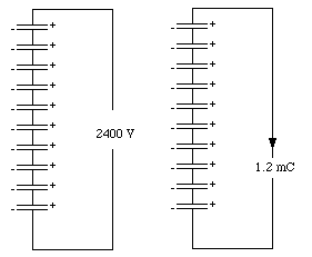
Ten identical 5 uF capacitors are connected in parallel to a 240-V battery. The charged capacitors are then disconnected from the battery and reconnected in series, the positive terminal of each capacitor being connected to the negative terminal of the next. What is the potential difference between the negative terminal of the first capacitor and the positive terminal of the last capacitor ? If these terminals are connected via an external circuit, how much charge will flow around this circuit as the series arrangement discharges ? How much energy is released in the discharge ? Compare this charge and this energy with the charge and energy stored in the original, parallel arrangement, and explain any discrepancies.
The charge on each capacitor, after being connected to the 240-V battery, is equal to
The potential difference across each capacitor will remain equal to 240 V after the capacitors are connected in series. The total potential difference across the ten capacitors is thus equal to

If the two end terminals of the capacitor network are connected, a charge of 1.2 mC will flow from the positive terminal to the negative terminal (see Figure 27.11).
The energy stored in each capacitor, after being charged to 240 V, is equal to
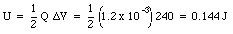
Clearly no energy is lost in the process of changing the capacitor configuration from parallel to serial.
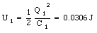
Three capacitors are connected as shown in Figure 27.12. Their capacitances are C1 = 2.0 uF, C2 = 6.0 uF, and C3 = 8.0 uF. If a voltage of 200 V is applied to the two free terminals, what will be the charge on each capacitor ? What will be the electric energy of each ?
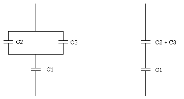
Suppose the voltage across capacitor C1 is V1, and the voltage across capacitor (C2 + C3) is V2. If the charge on capacitor C1 is equal to Q1, then the charge on the parallel capacitor is also equal to Q1. The potential difference across this system is equal to
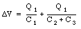
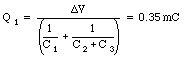
The charge on capacitor 1 is thus determined by the potential difference [Delta]V
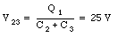
The voltage V23 across the capacitor (C2 + C3) is related to the charge Q1
The charge on capacitor C2 is equal to

The charge on capacitor C3 is equal to

The electric potential energy stored in each capacitor is equal to

For the three capacitors in this problem the electric potential energy is equal to