Problem 1
The configuration in this problem is equivalent to two capacitors, each of area A and plate distance d/2, in series. The capacitance of capacitor 1, which is filled with a dielectric with dielectric constant [kappa]1, is equal to
![]()
The capacitance of capacitor 2, which is filled with a dielectric with dielectric constant [kappa]2, is equal to
![]()
The total capacitance of these two capacitors in series is equal to

Using the values of the capacitance derived above we conclude that
![]()
Problem 2
The configuration in this problem is equivalent to two capacitors, each of area A/2 and plate distance d, in parallel. The capacitance of capacitor 1, which is filled with a dielectric with dielectric constant [kappa]1, is equal to
![]()
The capacitance of capacitor 2, which is filled with a dielectric with dielectric constant [kappa]2, is equal to
![]()
The total capacitance of these two capacitors in parallel is equal to
![]()
Using the values of the capacitance derived above we conclude that
![]()
Problem 3
The charge Q on a capacitor with capacitance C which is charged by a 140-V power supply is equal to
![]()
In order to store a certain charge Q we thus need a capacitor with a capacitance of
![]()
In order for the parallel plate capacitor to have this capacitance, the separation distance between the plates has to be equal to
![]()
Problem 4
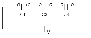
Consider the three capacitors in series. The total capacitance of this system can be obtained using the following equation:
![]()
The total capacitance is thus equal to
![]()
The total charge on the capacitor system is thus equal to
![]()
The charge on the various capacitors will be distributed as shown in the Figure. As a consequence, the charge on the positive plate of capacitor C2 is equal to
![]()

Figure Problem 4
Problem 5
The energy stored in a capacitor is given by
![]()
In this problem, the potential difference [Delta]V is fixed, and the energy stored in the capacitor can be changed by changing the dielectric. The capacitance of a parallel plate capacitor with a plate area A, a plated distance d, and a dielectric with dielectric constant [kappa] is equal to:
![]()
The energy store in the capacitor is thus equal to:
![]()
This equation shows that the maximum energy storage is achieved for the capacitor with the largest [kappa]/d.
Problem 6
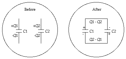
The configuration of the two capacitors is shown schematically in the following Figure.

Figure Problem 6.
Consider that after the connection is made, the charge on the positive capacitor plates of capacitor 1 and capacitor 2 are q1 and q2, respectively. After the connection is made, the potential difference across the two capacitors must be equal and thus
![]()
Also, since the total charge in the system is conserved, we must conclude that
![]()
Given these two equations with two unknown, q1 and q2, we can determine the final charges on the two capacitors:
![]()
![]()
The potential across the capacitor can not be calculated easily:
![]()
Problem 7
First consider the electric field between the conductors if no dielectric is present. This field is equal to
![]()
where [lambda] is the charge per unit length on the inner conductor. The electric field between the conductors will be reduced when the dielectric is inserted, and become
![]()
The potential difference between the two conductors can be obtained by evaluating the path integral of the electric field:
![]()
In this problem we consider a coaxial conductor of length L. If the total charge on the central conductor is Q, then the charge density [lambda] will be equal to Q/L. Thus:
![]()
The capacitance of this system is thus equal to

Problem 8
The capacitance of the coaxial cable of length L is equal to

The energy stored in this capacitor is equal to
![]()
NOTE: the length used in problem 8 is different from problem 7.
Problem 9
The current carried by a conductor depends on the dimensions of the conductor (length L and cross sections area A) , the density of charge carriers (n), and their drift velocity (vd). Consider a cylindrical shell of the conductor with inner radius r and outer radius dr. The total cross section area dA of this shell is equal to
![]()
During a time interval dt, all charge carried located with a distance vd dt will cross a certain point P on the shell. The total amount of charge flowing past P is thus equal to:
![]()
The current flowing past P is thus equal to
![]()
To find the total current carried by the wire we need to integrate the current dI over all cylindrical shells. For wire 1 we obtain:
![]()
For wire 2 we obtain:
![]()
The ratio between the current in wire 1 and the current in wire 2 is equal to:

Problem 10
The resistance of a conductor is equal to
![]()
where d is the diameter of the wire.
Problem 11
The power dissipated in the wire is equal to
![]()
Problem 12
The potential difference between the ends of the wire is equal to
![]()
Problem 13
The resistance of the wire is equal to
![]()
Consider a time period dt. During this time interval, all electrons within a length dL will pass past a certain point P:
![]()
The total number of electrons contained in this length of wire is equal to
![]()
The current that flows past P per unit time is thus equal to
![]()
The total power dissipated by this current in the wire is equal to
![]()