Proposal for the PHOBOS TOF wall
Submitted to the NSF, 12/95
Frank L. H. Wolfs
Department of Physics and Astonomy
University of Rochester, Rochester, NY 14627
I. Introduction
PHOBOS [1] is an approved experiment, one of four to be ready to run at the turn-on of the Relativistic Heavy-Ion Collider (RHIC) at Brookhaven National Laboratory. The goal of this experiment is to search for manifestations of new physics, such as the formation of a Quark-Gluon Plasma (QGP), under conditions of extreme energy density - the highest ever seen in a laboratory.
Although there have been extensive speculations about how the QGP may manifest itself, no one knows for sure what the unambiguous signature is of its formation. The PHOBOS experiment is designed to study as many collisions as possible, in an unbiased way, and to search for significant differences between p-p, p-A, and A-A collisions. A number of different physical parameters might provide information about the formation of the QGP. PHOBOS was optimized to study the following phase space regions and signals:
1. Temperature scale. If the system attains even approximate equilibrium, the temperature and energy density will be reflected in the Pt distribution. This will be crucial for determining the order of any phase transition. Even without equilibrium, large-scale collective effects should be reflected as a low Pt enhancement.
2. Time and distance scales. High precision Hanbury-Brown Twiss (HBT) correlations at low Pt will allow us to determine the relevant time and distance scales as well as dynamical effects such as expansion. These details of the reaction dynamics can provide information on the nature of the phase transition.
3. Flavor composition. The ratio of strange to non-strange quarks is expected to be higher in the QGP than in purely hadronic matter due to shorter equilibration times in the plasma. This should be reflected in variables such as the K/[[pi]] ratio.
4. Medium effects. The short lifetime of the [[phi]] meson and the small Q value of its decay into charged kaons makes it an ideal probe for the properties of the hadronic medium in which it forms. The important variable is the Pt dependence of the [[phi]] width.
5. Global variables. Events with an unusually large number of particles or unusually large fluctuations in dN/d[[eta]] d[[phi]] are likely to be characteristic of a phase transition. Furthermore, we can examine other signatures as a function of the global variables to search for correlated signatures.
The baseline design of PHOBOS relies solely on energy loss measurements to achieve particle identification. This technique allows K/[[pi]] separation up to a momentum of about 600 MeV/c and p/K separation up to about 1.2 GeV/c. This proposal requests funds for the addition of a time-of-flight wall, which will more than double the identified single-particle phase space of PHOBOS. This will, for example, double the phase space for reconstructable [[phi]] mesons and increase the HBT phase space by a factor of 16 (24).
The author and the PHOBOS collaboration [1] are convinced of the importance of the addition of a time-of-flight system. This view was also strongly endorsed by the RHIC Technical Advisory Committee Subpanel. We quote:
" The committee concurs with the collaboration that a time-of-flight system would significantly enhance the physics capabilities of PHOBOS and strongly encourages the continued search for additional collaborators who could provide such a system [2]. "
The time-of-flight system would have the following beneficial effects on PHOBOS physics:
1. Temperature scale. The time-of-flight system will more than double the Pt range over which we can uniquely identify pions and kaons. This will improve our lever arm for fits to the Pt distribution, allowing us to understand the functional form and look for any enhancements at low Pt.
2. Time and distance scales. The phase space for HBT will be doubled in EACH of the 4 different directions that we are interested in: QL, QTside, QTout, and MTpair. This is particularly important in the key variable QTside, where the baseline detector has limited acceptance and in the variable MTpair where lever-arm in phase space allows us to measure the dynamics of the source, such as expansion. Extending the phase space is particularly important for studying the p-p and p-A collisions where the source size is likely to be smaller and the required phase space in Q to be larger.
3. Flavor composition. The baseline particle identification relies on energy loss, and a time-of-flight measurement will allow us to cross-check the calibration of the particle identification even at low momentum, improving the systematics for all physics measurements which use the spectrometer as well as increasing the phase space over which we make the measurements.
4. Medium effects. The phase space for the [[phi]] meson in Pt is also doubled (or more) by the time-of-flight system while the statistics are tripled. The baseline detector measures an interesting corner of the [[phi]]-meson phase space, but has no lever-arm in Pt to see any interesting effects turn off with increasing Pt as the [[phi]] meson spends less time in the medium in its own rest frame.
5. Global variables. The PHOBOS multiplicity detector measurements are also based on energy deposition and therefore rely on knowledge of the underlying momentum distribution for calibration. The time-of-flight system will allow a better measurement of this momentum distribution, significantly improving the systematics near mid-rapidity.
These improvements would represent qualitative jumps in the physics capabilities rather than incremental ones at a cost which is only 25 % of the baseline detector. By funding this extension the NSF can make a significant improvement to the physics program of RHIC.
This proposal is organized as follows. In Section II the PHOBOS detector is briefly described. The limitations of particle identification on the basis of energy loss measurements is discussed in Section III. This Section also contains a discussion of the use of time-of-flight to extend the range of incident momenta for which particle identification can be achieved. In Section IV the impact of the addition of a time-of-flight wall on the physics program that can be carried out with PHOBOS is summarized. The design of the PHOBOS time-of-flight wall is discussed in Section V, and the calculated acceptance of the time-of-flight wall will be described in Section VI. In Section VII the electronics required to process the signals from the time-of-flight wall will be summarized. The proposed construction schedule is presented in Section VIII, and the cost of the project is summarized in Section IX. The proposal is summarized in Section X.

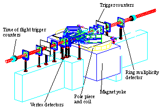
Figure 1: Schematic view of the PHOBOS detector.
II. Overview of the PHOBOS detector.
The PHOBOS detector is schematically shown in Figure 1. The major components of the system are the multiplicity and vertex detectors and the two-arm multi-particle spectrometer. The multiplicity barrel covers 85% of the total solid angle around the interaction point and covers a pseudo rapidity range of -2.5 < [[eta]] < + 3.4. The multiplicity ring counters, mounted along the beam pipe on either side of the interaction region, extend the range of pseudo rapidity up to [[eta]] = +/- 5.4. The pseudo rapidity range between 5.4 and 5.7 is covered by a ring of Cerenkov counters. The two-arm multi-particle spectrometer covers 1% of the total solid angle and has been optimized for good acceptance of particles with + 0.5 < [[eta]] < + 1.5. Each arm of the spectrometer is situated in the gap of a high-field room-temperature magnet.
The PHOBOS experiment has been designed conservatively for simplicity and flexibility and is based on proven technology [1]. All elements of the multiplicity and vertex detectors and the multi-particle spectrometer are made of silicon. This greatly simplifies the high-density front-end electronics and the data acquisition scheme.
The issue of flexibility is important in the exploration of new physics at RHIC. Since the signal of the interesting physics is speculative, the PHOBOS spectrometer was designed to provide maximum flexibility in its acceptance. For example, if the average multiplicity is dramatically greater than expectations, the distance of the spectrometer to the interaction region can be increased, thereby decreasing the occupancy to an acceptable level, at the cost of a reduction in the azimuthal acceptance.
III. Particle Identification.
Particle identification in the PHOBOS spectrometer relies on various energy-loss and momentum measurements [1]. The limitations of the various particle identification techniques has been studied in detail with Monte-Carlo simulations of the PHOBOS spectrometer based on the code GEANT.
In the low momentum region (p[[pi]] < 55 MeV/c, pK < 135 MeV/c, pp < 225 MeV/c) the energy loss depends strongly on velocity of the ions, and the particles stop in the first seven silicon detector planes. The ions can be identified using their measured energy loss in the first detector plane(s) and their total energy (obtained by summing all the energy losses).
For larger momenta the particles enter the magnet gap and their momenta can be measured. A measurement of the energy loss combined with the results of a momentum analysis can be used for particle identification. Figure 2 shows the energy loss in six out of ten detector planes as a function of the incident momentum for pions, kaons, and protons (the four planes with the highest measured energy loss are not included). This technique allows K/[[pi]] separation up to about 600 MeV/c and p/K separation up to about 1.2 GeV/c.
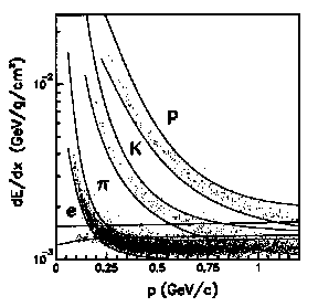
Fig.2. Energy loss in the six out of ten silicon planes as a function of the incident momentum for pions, kaons and protons.
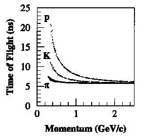
Fig.3 Time of flight as function of incident momentum for a time-of-flight detector located 1.70 m from the interaction point.
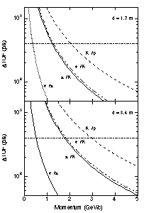
Fig. 4. Time-of-flight difference between various particles as function of their momenta for a time-of-flight wall at a distance of 1.7 m and 3.4 m from the interaction point. The dot-dashed horizontal lines correspond to a 4[[sigma]] time-of-flight difference, assuming a 100 ps time-of-flight resolution.
The particle-identification capability of PHOBOS can be extended significantly by the addition of a time-of-flight wall. This is illustrated in Figure 3 where the time of flight is shown as a function of the incident momentum for pions, kaons, and protons, for a time-of-flight wall located 1.7 m from the interaction point. Figure 4 shows the difference in the time of flight for various particles as a function of their momenta for a flight path of 1.7 m and 3.4 m. The dashed-dotted horizontal lines in Figure 4 correspond to a 4[[sigma]] time-of-flight difference, assuming a 100 ps time-of-flight resolution. Using the time-of-flight information, the range of [[pi]]/K separation is extended from about 600 MeV/c to about 1.2 GeV/c (d = 1.7 m) and 1.8 GeV/c (d = 3.4 m), and the range of K/p separation is extended from about 1.2 GeV/c to about 2.0 GeV/c (d = 1.7 m) and 2.9 GeV/c (d = 3.4 m). In addition, electrons can be separated from pions up to about 350 MeV/c (d = 1.7 m) and 500 MeV/c (d = 3.4 m), and from kaons up to about 1.3 GeV/c (d = 1.7 m) and 1.8 GeV/c (d = 3.4 m).
IV. Physics Impact
Extending the momentum range within which particles can be uniquely identified extends the measurable phase space in two ways. For particles with a large angle relative to the beam - or small rapidity - we extend the Pt coverage. For small angles, we extend the rapidity coverage for a fixed vertex position. This is illustrated in Figure 5 which shows acceptance regions in rapidity and transverse momentum for pions. The extension of phase space provided by the time-of-flight system is apparent.
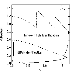
Fig. 5. Acceptance regions in rapidity and transverse momentum for pions. The various regions in this Figure are labeled according to the technique that will be used to achieve particle identification. The "saw-tooth" structure of the dotted curve is a results of the segmentation of the time-of-flight wall.
For single particle spectra, this extension to a higher transverse momentum will allow us to study the spectral behavior at low Pt in detail. Comparing the low Pt yield to extrapolations from higher Pt provides considerably more information than the model-dependent procedure of just comparing shapes and yields of low Pt particles to predictions of dynamical calculations. Figure 6 illustrates the fact that the addition of a time-of-flight system will allow a more comprehensive characterization of the overall shape of the momentum distributions, resulting in more convincing evidence for any interesting effects seen at low Pt.
The effect of the time-of-flight system is even more dramatic on multi-particle measurements such as reconstructing the [[phi]] meson and measuring HBT source size/lifetime parameters. The Pt reach of the [[phi]] measurement is also doubled and the statistics are tripled. This is particularly important for the [[phi]] because the amount of time that it spends in the hot hadronic medium (in its own rest frame) is a function of Pt. For the HBT source size/lifetime measurement, extending the momentum coverage by a factor of 2 - 3 also extends the coverage in the variables QL, QTside, QTout, and MTpair by the same amount.
The QL and QTout ranges are 0 - 0.5 GeV/c without the time-of-flight system and are extended to 0 - 1.1 GeV/c when the time-of-flight system is included. This improves the normalization on all of our multi-dimensional fits for A-A and especially for p-p where the source is smaller and the Q-extension of the correlation function larger. Even more critically, the QTside range is improved from 0 - 100 MeV/c to 0 - 200 MeV/c. This is essential for finding the geometric size of the source uncontaminated by effects of the duration of particle emission. Finally, the MTpair distribution is extended (for pions) from 0.14 - 0.55 GeV/c2 to 0.14 - 1.1 GeV/c2 which allows us to sort out the dynamical correlations and see the effect of expanding sources. The MTpair coverage of the kaons is extended from 0.50 - 0.73 GeV/c2 to 0.50 - 1.2 GeV/c2. The key point here is that the MTpair coverage of the pions and the kaons will overlap if we use the time-of-flight system. This will allow us to check species-independence at fixed MTpair before trying to use both species together to draw a conclusion as well as providing a good MTpair lever-arm for each species alone.
Clearly the addition of a time-of-flight system to the PHOBOS experiment will significantly improve the phase space acceptance of the detector for identified particles. This, in turn, will significantly improve its physics capabilities.
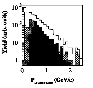
Fig.6. Measured PT distributions for 100 typical high-occupancy events for those particles whose linear momentum can be measured with the spectrometer (open histogram), for those that also interact with the time-of-flight wall (cross-hatched and solid histograms), and for those that can not identified on the basis of energy-loss information in the spectrometer but can be identified on the basis of a time-of-flight measurement (solid histogram).
V. Design
In order to achieve the design goals outlined in Section III the time-of-flight resolution of the time-of-flight wall must be better than 100 ps. This resolution has been achieved by various time-of-flight detector systems that are currently being used at for example the AGS or are evaluated for use at RHIC. Table 1 summarizes important properties of these time-of-flight detector systems and their demonstrated time-of-flight resolution.
         E802       E813/E836 E866         BRAHMS     PHENIX      STAR
Material BC404      BC408     BC404        BC404      BC404       BC404  BC408
                                                                  BC420
Size     1.6x1.6x78 8.5x5x200 1.25x1.25x42 0.6x0.6x22 1.2x1.2x85  1.5x2.5x25 (404)
(cm3)                                      0.4x0.4x22 0.8x0.8x130 1.5x1.5x42 (408)
                                                                  1.5x1.5x42 (420)
PM Tubes R2083      H1949     R3478S       R1635      R3478S      R3432
                                           R3478S
delta T  75 ps      110 ps    77 ps        62 ps      75 ps       94 ps (404)
                                                                  69 ps (408)
                                                                  56 ps (420)
Refer.   [3]        [4]       [5]          [6]        [7-9]       [10]
Table 1. Summary of properties of various time-of-flight detector systems that are
currently in use at for example the AGS or are evaluated for use at RHIC. All
scintillators listed in this table are produced by the Bicron Corporation. All
photomultiplier tubes listed in this table are produced by Hamamatsu.BC404, made by the BICRON Corporation, will be used as the scintillating material for the proposed time-of-flight wall. It has good timing characteristics (a 1.8 ns decay constant) and a moderate attenuation length (1.6 m). Its wavelength of maximum emission (408 nm) is close to the wavelength at which the response of most fast photomultiplier tubes peak (420 nm). The scintillator segments will be 20 cm high and have a cross sectional areas of 1.0 x 1.0 cm2 and 0.8 x 0.8 cm2. Table 2 summarizes the relevant dimension of the scintillator segments to be used for the proposed time-of-flight wall.
The photomultiplier tubes to be used must have a fast rise time (<= 1.8 ns), high gain (>= 1 x 10⁶), and have a diameter similar to the cross sectional area of the scintillator (to facility close packing). Table 3 lists the photomultiplier tubes that are considered for the time-of-flight wall. It is noteworthy that the BRAHMS collaboration has evaluated time-of-flight segments with dimensions very similar to the PHOBOS segments and a time resolution of 62 ps has been achieved with 10 mm diameter (R1635) and 19 mm diameter (R3478S) photomultiplier tubes.
Two photomultiplier tubes will be coupled, via light guides, to the end of each scintillator segment. A simultaneous measurement of the time and pulse height allows slewing corrections to be made, which was found necessary in various other studies in order to achieve time-of-flight resolutions better than 100 ps. The time-of-flight information used for particle identification will be the average of the time-of-flight information provided by the individual photomultiplier tubes. The time-of-flight information provided by the individual photomultiplier tubes will also be used to determine the vertical position of the incident particles. Based on a timing resolution of 100 ps for each photomultiplier tube it is estimated that the vertical position resolution is about 2 cm. The vertical position is a very important parameter since it will greatly enhance our capabilities to match the particle tracks measured in the spectrometer with the hits recorded in the time-of-flight wall. If more than two particles hit one scintillator segment, then the timing information is lost. However, in many cases, this type of events can be recognized and identified by checking the consistency of the time difference between the two photomultiplier tube signals and the ratio of their pulse heights. Needless to say, the current design of the time-of-flight wall aims at keeping the double-hit probability as low as possible.
                            20 - 30 deg.  30 - 50 deg.  50 - 90 deg.
Number of Segments             120           120           120
Distance from Interaction      5.50          2.75          1.70
Point (m)
Segment size (cm3)          0.8x0.8x20    0.8x0.8x20    1.0x1.0x20
Opening Angle (mrad)           1.5           2.9           5.8
Table 2. Dimensions of the various scintillator segments to be used for the PHOBOS time-of-flight wall. The angles indicated in the top row are measured with respect to the beam. Note that currently no funding is requested to provide coverage in the angular range between 20deg. and 30deg.
                         R1635        R4124        R3478S
Diameter (mm)              10           13           19
Response Range (nm)     300 - 650    300 - 650    300 - 650
Peak Wavelength (nm)      420          420          420
Supply Voltage (Vdc)     1250         1000         1700
Current Amplification   1.1 x 10E6   1.1 x 10E6   1.7 x 10E6
Rise Time (ns)            0.8          1.1          1.3
Transit Time (ns)         7.8           12           14
Table 3. Summary of the photomultiplier tubes that are considered to be used for the PHOBOS time-of-flight wall.
The segmentation of the time-of-flight wall is determined by the requirement that the average occupancy is less than 15% for a "standard event" which is an event for which the charged particle rapidity density dN/dy = 1000 at y = 0, which corresponds to a typical high-occupancy event. Figure 7 shows the results of GEANT simulations of the proposed PHOBOS time-of-flight wall obtained for 100 "standard" events. Figure 7a shows the average measured yield per event per 5deg. of primary particles, particles produced at the interaction point, as a function of the angle with respect to the beam. Figure 7b shows the same thing as Figure 7a, except for secondary particles, particles not produced at the interaction point. The segmentation of the proposed time-of-flight wall, summarized in Table 2, was chosen such that the average occupancy is about 15%. Figure 7c shows the calculated occupancy obtained from these simulations as a function of the angle with respect to the beam. The jumps in the occupancy at +/- 50deg. and at +/- 30deg. are associated with the change in the segmentation that occurs at these angles. Figure 8 shows a schematic layout of the PHOBOS detector with the proposed time-of-flight wall.
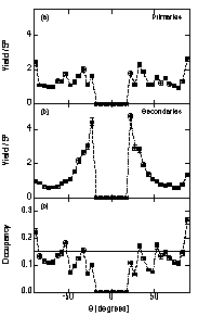
Fig. 7. (a) Average yield of primary fragments detected in the time-of-flight wall as a function of the angle with respect to the beam for a central standard event. (b) As (a) but for secondary fragments. (c) Calculated occupancy for the proposed time-of-flight wall as a function of the angle with respect to the beam. The error bars shown in this Figure are statistical errors.
Note that the current proposal does not request funds for the segments of the time-of-flight wall covering the angles between 20deg. and 30deg. with respect to the beam. However, in the current design and in the simulations discussed here, the segments between 20deg. and 30deg. are identical to the segments covering the angles between 30deg. and 50deg.. Therefore, for part or all of the running time we can choose to move one of the segments of the time-of-flight wall, covering the angles between 30deg. and 50deg., into a position that covers the angles between 20deg. and 30deg.. Thus, the time-of-flight wall, like the rest of the PHOBOS detector, is flexible enough to be adjusted to whatever conditions we find at RHIC or whatever new physics priorities we come up with after seeing the actual data.
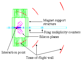
Fig. 8. Schematic layout of the PHOBOS detector with the proposed time-of-flight wall. Note that the 50deg. - 90deg. segments of the time-of-flight wall are located inside the magnet support structure.
The 480 scintillator segments of the time-of-flight wall have each a height of 20 cm, and a cross sectional area of 1 x 1 cm2 for those located between 50deg. and 90deg. and 0.8 x 0.8 cm2 for those located between 30deg. and 50deg.. The scintillator segments are optically isolated by wrapping them in aluminum foil and 16 segments are combined to form a "standard" building block of the time-of-flight wall. Photomultiplier tubes are connected to the scintillator segments via BC 800 light guides (see Figure 9). The light guides are also used to slightly offset the location of neighboring photomultiplier tubes which is necessary since the width of the scintillator segments is smaller than the diameter of the photomultiplier tubes. The shape of the light guides is chosen such that the symmetry axis of the photomultiplier tubes is located along the vertical direction.
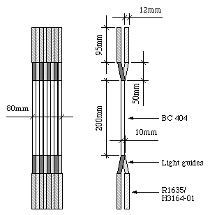
Fig. 9. Schematic drawing of a building block of the time-of-flight wall. This building block will be part of the section that is located between 50deg. and 90deg.. The scintillator segments of the section located between 30deg. and 50deg. have a cross sectional area of 0.8 x 0.8 cm2, but their design is similar to the design shown here.
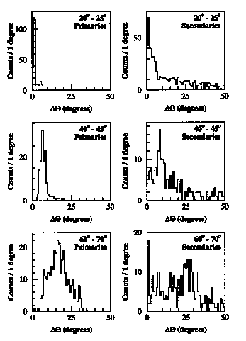
Fig.10. Angle difference between trajectory of the incident fragment and the normal to the scintillator surface. The left and right histograms show this difference for primary and secondary fragments, respectively, at several sections of the time-of-flight wall.
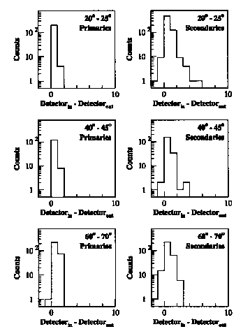
Fig.11. Difference between the detector number of the scintillator where the fragment entered the time-of-flight wall and the detector number of the scintillator where the fragment exited the time-of-flight wall for primary and secondary fragments at several sections of the time-of-flight wall.
The actual count rate in each detector element is slightly higher than the rate predicted on the basis of the occupancy shown in Figure 7. This is due to the fact that the angle of incidence of the particles onto the surface of the scintillator is less than 90deg., and consequently some tracks will produce a signal in more than one scintillator segment. Figure 10 shows the difference between the angle of incidence and the normal of the scintillator surface for three different segments of the time-of-flight wall. This angle difference is limited to a specific range of angles for primary fragments, while the distributions for secondary fragments are significantly wider. Figure 11 shows the difference between the detector number of the scintillator where the fragment entered the time-of-flight wall and the detector number of the scintillator where the fragment exited the time-of-flight wall. A number different from zero indicates that that particular fragment will produce a signal in more than one scintillator segment. Figure 11 shows that this happens much more frequently for secondary fragment compared to primary fragments. The probability of hitting more than one scintillator segment is largest for those segments that are mounted at large angles with respect to the beam direction. The probability that more than one segment is hit can be reduced by changing the orientation of the scintillator segments such that the angle of incidence is closer to normal. Such a reorientation has the biggest effect for the segments located at large angles, where a rotation by 15deg. - 20deg. is envisioned. This rotation will primarily reduce the multiple-triggering probability for primary fragments, and have less of an effect on the secondary fragments. Further studies are needed to determine the optimum orientation of the scintillator segments.
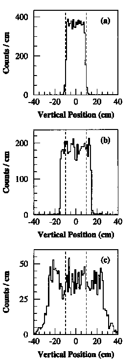
Fig. 12. Vertical position at the location of the time-of-flight wall of those primary fragments that pass through all the silicon detector planes for (a) the 50deg. - 90deg. section, (b) the 30deg. - 50deg. section, and (c) the 20deg. - 30deg. section. The dashed lines indicate the vertical positions that are covered by the proposed time-of-flight wall.
VI. Acceptance
The acceptance of the time-of-flight wall has been studied extensively. To achieve the desired occupancy without increasing the number of scintillators beyond 500 it was necessary to reduce the vertical acceptance of the time-of-flight wall. Figure 12 shows the vertical position of primary fragments that pass through all the silicon planes of the spectrometer at the position where the time-of-flight wall is located. Figure 12a shows that all primary fragments that can be detected with the 50deg. - 90deg. section of the time-of-flight wall have a vertical position that coincides with the sensitive area of the scintillator (-10 cm <= y <= +10 cm). The particles that can be detected with the 30deg. - 50deg. section of the time-of-flight wall are distributed uniformly in the vertical direction with -15 cm <= y <= +15 cm (see Figure 12b). The efficiency to detect these particles is close to 70% since the height of the scintillator is less than the height required to detect the particles with a 100% efficiency. It is possible to increase the height of the scintillator from 20 cm to 30 cm after it has been demonstrated that a 50% higher occupancy can be tolerated. The estimated cost of this improvement is about $ 30,000, which is essentially the cost of new scintillator segments. In the design of the support structure, the possibility of this future upgrade will be taken into account. The particles that can be detected with the 20deg. - 30deg. section of the time-of-flight wall are distributed uniformly in the vertical direction with -30 cm <= y <= +30 cm (see Figure 12c). The efficiency to detect these particles is close to 40% since the height of the sensitive area is significantly less than the height required to detect the particles with a 100% efficiency.
The momentum acceptance of the time-of-flight wall has been studied using GEANT simulations in which particles with a momentum uniformly distributed between 0 GeV/c and 2.5 GeV/c are isotropically emitted from the interaction point into the acceptance of the spectrometer. Figure 13 shows the detection angle on the time-of-flight wall, relative to the beam direction, as a function of the momentum for those particles that travel through all the silicon planes of the spectrometer. The solid and dashed vertical lines in Figure 13 indicate the momentum above which [[pi]]/K and K/p separation can no longer be achieved on the basis of only energy loss measurements. Most of the acceptance of the time-of-flight wall covers a range of momenta where a time-of-flight measurement is the only feasible method of particle identification. Figure 14a shows a projection of the acceptance shown in Figure 13 on the momentum axis. The solid and dashed vertical lines in Figure 14 indicate the momentum above which [[pi]]/K and K/p separation requires the use of the time-of-flight wall. The acceptance of the time-of-flight wall increases with increasing momentum below about 1 GeV/c. For larger momenta the acceptance increases significantly slower with increasing momentum. The small acceptance of the time-of-flight wall below 0.5 GeV/c is associated with the large deflections of low-momentum ions in the magnetic field of the spectrometer, which results in them being deflected towards angles larger than 90deg. (and therefore outside the acceptance of the time-of-flight wall). On the other hand, since the simultaneous measurement of the energy loss and momentum can be used for particle identification in the low-momentum regime, this reduction in acceptance does not lead to a reduction in particle identification efficiency for low-momentum ions. Figure 14b shows the number of particles in the simulations that travel through all the silicon planes of the spectrometer but do not make it to the time-of-flight wall as a function of their momentum. The yield decreases with increasing momentum. Most particles in the low-momentum region can be identified on the basis of a simultaneous energy loss and momentum measurement.
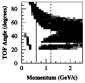
Fig.13. Results of GEANT simulations showing the detection angle of particles on the time-of-flight wall as a function of their momentum. The solid and dashed lines indicate the momenta beyond which K/[[pi]] and p/K separation, respectively, requires the use of the time-of-flight wall.
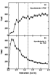
Fig. 14. Results of GEANT simulations in which particles with a momentum distributed randomly between 0 GeV/c and 2.5 GeV/c are emitted isotropically from the interaction point. The number of particles that pass through all the silicon planes and through the time-of-flight wall is shown in (a) as a function of the incident momentum. The number of particles that pass through all the silicon planes but do not pass through the time-of-flight wall is shown in (b).
VII. Electronics
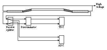
Fig.15. Schematic of the electronics associated with a single scintillator segment.
A schematic of the electronics associated with a single scintillator segment is shown in Figure 15. For each photomultiplier tube the pulse height and the timing information is recorded. The pulse height information is required to be able to make slewing corrections, which are required in order to achieve time-of-flight resolutions of 100 ps or better. All electronics, except the passive splitter, are commercially available, and thus require no development.
The high voltage (HV) for the photomultiplier tube is supplied by a LeCroy 1458 HV Mainframe. Each channel of this supply can provide a maximum current of 3.1 mA. Since the bleeder current of the photomultiplier tubes is around 0.5 mA we plan to connect four photomultiplier tubes to a single channel of the HV supply.
The signal from each photomultiplier tube is split with a home-built passive two-way splitter. One signal is send to a LeCroy 1881M 13-bit FASTBUS Analog-to-Digital Converter (ADC). The other signal is send to a LeCroy 3412 CAMAC discriminator. The ECL output of this discriminator is converted with a LeCroy 1875A 15-Bit FASTBUS Time-to-Digital Converter (TDC). FASTBUS was chosen for signal processing on a purely economical basis. Both CAMAC and VME were considered, but the lower channel densities led to a significant increase in the electronics cost. In addition, in order to achieve a time resolution better than 100 ps a high-resolution TDC is required, and very few commercially available TDCs have the required resolution.
Both the energy and the timing signals are delayed by about 150 ns with 100 ft of cable delay in order to process the information from the trigger counters and generate the gate and start for the ADC and TDC.
VIII. Schedule
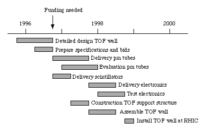
Fig. 16. Time line of the PHOBOS time-of-flight wall construction project.
The overall schedule of the construction of the PHOBOS time-of-flight wall is shown in Figure 16. In order to complete the construction of the time-of-flight wall before the first beam will be available at RHIC, which currently is scheduled to occur in April 1999, funding must start in October 1996. Before October 1996, a series of prototype counters will be build and tested and the final design of the wall will be agreed upon. The major items to be purchased are the photomultiplier tubes, the scintillators, and the electronics. It is estimated that Hamamatsu can deliver at least 100 photomultiplier tubes per month, and this order would be completed roughly 1 year after the start of funding. The scintillator segments can be produced at a rate of about 100 segments per man-month. This order therefore will also be completed roughly one year after the start of funding. The electronics will be ordered in the beginning of 1998. Delivery time for all components is less than six months.
IX. Cost
The major costs of the time-of-flight wall are the photomultiplier tubes and the various electronics components. The cost of the time-of-flight hardware, excluding the electronics, is listed in Table 4. This table lists 3 different scenarios, that differ on the basis of the type of photomultiplier tube that is being used. The BRAHMS collaboration has shown that a time-of-flight resolution of better than 100 ps can be achieved using either the R3478S or the R1635 (H3164-01 assembly) photomultiplier tubes. We are not aware of any group that has attempted to achieve time-of-flight resolutions better than 100 ps with the R4124 photomultiplier tubes. On the other hand, as indicated in Table 3, the properties of this photomultiplier tube are similar to those of the R3478S and R1635 photomultiplier tubes, suggesting that a time-of-flight resolution of better than 100 ps can be achieved with the R4124 photomultiplier tube. Due to the cost implications we plan to study the response of the R4124 in detail before a final decision is made on the type of photomultiplier tubes that will be used for the time-of-flight wall.
Item                          Quantity   Unit Price  Cost 3478S  Cost 4124   Cost 3164
Hamamatsu R3478S PM (19 mm)     990      $ 514.12    $ 508,978
Magnetic Shields                990      $  35.59    $  35,234
PM Base                         990      $ 144.90    $ 143,451
Hamamatsu R4124 PM (14mm)       990      $ 488.19                $ 483,308
Magnetic Shields                990      $  28.78                $  28,492
PM Base                         990      $  74.54                $  73,794
Hamamatsu H3164-01 PM           990      $ 698.10                            $ 691,119
0.8 x 0.8 x 20 cm3 BC-420       400      $  28.50    $  11,400   $  11,400   $  11,400
1.0 x 1.0 x 20 cm3 BC-420       200      $  32.10    $   6,420   $   6,420   $   6,420
Light Guides                    1080     $  10.00    $  10,800   $  10,800   $  10,800
                                             Total:  $ 716,284   $ 614,215   $ 719,739
Table 4. Cost estimate of hardware for the proposed time-of-flight wall.The cost of the electronics for the time-of-flight wall is summarized in Table 5. The electronics is, where possible, based on FASTBUS, mainly because of cost implications. The beam-left and beam-right segments of the time-of-flight wall share the HV mainframe. The discriminators, ADCs and TDCs for the beam-left and beam-right segments resides in separate crates, mounted as close as possible to the time-of-flight wall. The BRAHMS collaboration has demonstrated that the time resolutions of 62 ps can be obtained with the R1635 photomultiplier tubes when the distance between the tube and the discriminator is 50 ft. In our configuration, the longest distance between photomultiplier tube and discriminator will be around 10 - 15 ft, and consequently no significant deterioration of the photomultiplier tube signals is expected.
The cost of the design and fabrication of the support structures is estimated to be $ 80,000. The cost of labor associated with polishing and assembling the individual scintillator segments is estimated to be $ 50 per segment, corresponding to a total cost of $ 20,000 for the whole time-of-flight wall. It is here assumed that undergraduate students from the University of Rochester are hired for this task.
The cost of the proposed time-of-flight wall is $ 1,484,536.90. Including a 15% contingency the final cost is estimated to be $ 1,707,217.44. These funds are requested over a two year period. During the first year funds are requested for the purchase of the photomultiplier tubes, the scintillators, and the light guides. The associated cost is estimated to be $ 739,739 which becomes $ 850,699.85 when the 15% contingency is included. During the second year the electronics will be purchased and the support structure will be build. The associated cost is estimated to be $ 744,447 which becomes $ 856,114.05 when the 15% contingency is included.
Item                            Quantity    Unit Price    Cost
HV Cards                           22       $ 1,440.00    $ 31,680.00
HV Power Supply Crate              2        $ 8,517.50    $ 17,035.00
Discriminators                     62       $ 1,650.00    $ 102,300.00
TDCs                               18       $ 4,640.00    $ 83,520.00
ADCs                               18       $ 6,445.00    $ 116,010.00
FASTBUS Crates                     2        $ 13,535.00   $ 27,070.00
FASTBUS Calibration Cards          2        $ 3,390.00    $ 6,780.00
FASTBUS Interface                  2        $ 5,146.00    $ 10,292.00
CAMAC Crates                       4        $ 6,045.00    $ 24,180.00
VME/VSB CAMAC controller           4        $ 2,488.00    $ 9,952.00
HV Cables RG 59                50,000 ft    $ 0.62        $ 31,000.00
Timing-Signal Cables RG 213/U  50,000 ft    $ 0.92        $ 46,000.00
Twisted Pair, 34 Conductors     6,400 ft    $ 1.39        $ 8,896.00
Energy-Signal Cables           100,000 ft   $ 0.92        $ 92,000.00
SHV Connector                     1000      $ 19.95       $ 19,152.00
BNC Connector                     1000      $ 4.74        $ 4,740.00
LEMO Connector                    3000      $ 11.28       $ 33,840.00
                                                  Total:  $ 664,447.00
Table 5. Cost estimate of electronics for the proposed time-of-flight wall.
X. Summary
PHOBOS is one of four detectors that will have the first look at the extreme energy densities that will be created when gold nuclei collide at RHIC. It has the potential of a major scientific discovery.
The addition of a time-of-flight system will significantly increase the capability of the PHOBOS detector and thus its potential for discovery. This system will more than double the region in phase space where particles can be identified. The addition of a time-of-flight system not only has strong support from the PHOBOS collaboration but also has been enthusiastically received by the RHIC detector Technical Advisory Committee Subpanel.
There are no unresolved technical issues involved in building the proposed time-of-flight system and our group has the experience and capability to carry out the proposed project.
By funding this proposal the NSF can have a significant impact on the RHIC research program in a cost effective manner.
REFERENCES
[1] The PHOBOS Collaboration, The PHOBOS Conceptual Design Report, 1994 (Unpublished).
[2] RHIC Technical Advisory Subpanel, Report of the Technical Advisory Committee Subpanel on the PHOBOS Conceptual Design, 1994 (Unpublished).
[3] T. Abbott, M. Abreu, Y. Akiba, D. Alburger, D. Beavis, R.R. Betts, L. Birstein, M.A. Bloomer, P.D. Bond, C. Chasman, Y.Y. Chu, B.A. Cole, J.B. Costales, H.J. Crowford, J.B. Cumming, R. Debbe, E. Duek, H. Enge, J. Engelage, S.Y. Fung, L. Grodzins, S. Gushue, H. Hamagaki, O. Hansen, P. Haustein, S. Hayashi, S. Homma, H.Z. Hunag, Y. Ikeda, I. Juricic, S. Katcoff, S. Kaufman, K. Kimura, K. Kurita, R. Lanza, R.J. Ledoux, M.J. Levine, M. Mariscotti, Y. Miake, R.J. Morse, S. Nagamiya, J. Olness, C.G. Parsons, L.P. Remsberg, M. Sarabura, A. Shor, P. Stankus, S.G. Steadman, G.S.F. Stephans, T. Sugitate, M. Tanaka, M.J. Tannanbaum, M. Torikoshi, J.H. van Dijk, Videbaek F, P. Vincent, E. Vulgaris, V.Vutsadakis, B. Wadsworth, W.A. Watson III, H.E. Wegner, D.S. Woodruff, Y.D. Wu, and W.A. Zajc, A Single Arm Spectrometer Detector System for High-Energy Heavy-Ion Experiments, Nucl. Instr. and Meth. A290 (1990) 41.
[4] V. Sum, A.R. Berdoz, C.A. Davis, S.A. Page, W.D. Ramsay, W.T.H. van Oers, R.A. Schumacher, V.J. Zeps, D.R. Gill, T. Iijima, K. Okada, and F. Takeutchi, A Time-of-flight Array for 1 to 2 GeV/c Particles, Nucl. Instr. and Meth. A326 (1993) 489.
[5] K. Shigaki, Study of Hadron production in Au + Au Collisions at 10.9 A GeV/c with a new Forward-Angle Spectrometer, Doctoral Thesis University of Tokyo, 1995 (Unpublished).
[6] The BRAHMS Collaboration, The BRAHMS Conceptual Design Report, 1994 (Unpublished).
[7] The PHENIX Collaboration, The PHENIX Conceptual Design Report, 1992 (Unpublished).
[8] X.H. Yang, T.K. Nayak, C.Y.Chi, B.A. Cole, S. Nagamiya, W.A. Zajc, and Y. Miake, Monte-Carlo Studies of the Performance of Scintillator Detectors for Time-of-flight Measurements, Nucl. Instr. and Meth. A354 (1995) 270.
[9] M. Kurata, S. Kato, A. Kumagai, K. Kurita, Y. Miake, S. Sato, K. Tomizawa, S. Ueno-Hayashi, K. Yagi, S. Nagamiya, T.K. Nayak, O. Vossnack, X. Yang, and W. Zhan, Study of Timing Degradation and Light Attenuation in Long Plastic Scintillation Rods for Time-of-flight Counters in Relativistic Heavy-Ion Experiments, Nucl. Instr. and Meth. A349 (1994) 447.
[10] S. Ahmad, B.E. Bonner, W. Gere, G.S. Mutchler, P. Rambo, S. Toshkov, E. Platner, H.J. Crawford, and J.M. Engelage, In-beam Tests of Proximity Mesh Dynode Tubes for the STAR TOF Subsystem, Nucl. Instr. and Meth. 1993 (1993) 416.