LeCroy 1458 HV
Mainframe Slow Controls Manual
I. Getting Started.
- Double click HV Control Icon on Desktop.
- Start Running HV Control Program by pressing arrow icon in
upper left corner of screen.
- The program will prompt you to select a template file (HV_latest
file is the file with the most recent values) to load desired
values into mainframe. These files are located in the directory
c:/Users/Tof/template files/HV control. This template file has
a specific format to be shown later. (See section IV)
- The Program will load all the desired values from template
into the mainframe automatically. (This will take ~10 mins.)
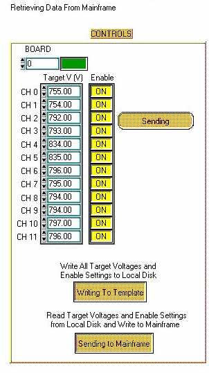
- Next, the program will read measured values from mainframe
and write to database. There should be a message on screen just
above the Controls saying "Retrieving Data from Mainframe".
You will not be able to control mainframe when you see this message.
II. Controlling the Program.
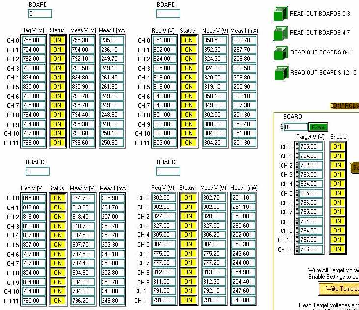
A. Reading setting and measured values.
Click Read Out Boards x-y to display boards x-y in read out
tables.
CH = channel. Range is 0-11.
Req V = Requested Voltage.
Meas V = Measured Voltage.
Meas I = Measured Current.
Status = On for Enabled/ Off for disabled.
Board = Slot number/ Board Number given on the rear of the
mainframe. Range is 0-15.
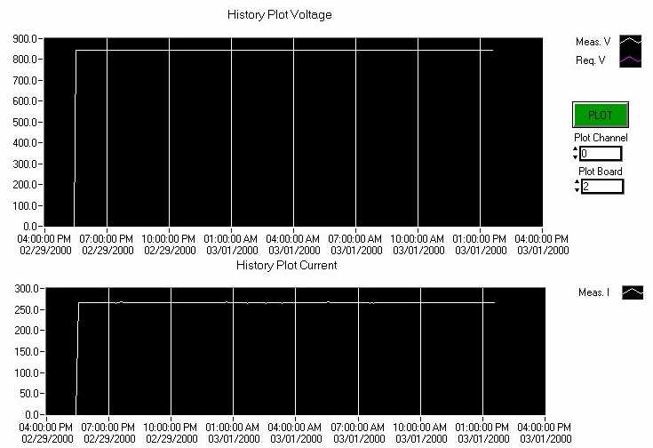
B. Plotting specific channel over a maximum
of 24 hours.
- Go to the History Plot section.
- Enter desired board number and channel number on that board.
- Click Plot Button.
- Program will plot the measured current in History Plot Current
(white) and the requested voltage (blue) and measured voltage
(white) in the History Plot Voltage for the desired channel.
All controls listed
below are locked out when the program is retrieving data from
the mainframe.
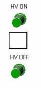
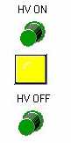
C. Turning HV on and off.
- To turn on HV click HV ON Button.
- To turn off HV click HV OFF Button.
- HV LED is Yellow when HV is on and is white when it is off.
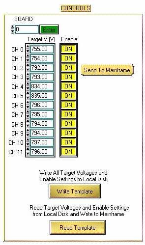
D. Changing Voltages and Enabling or Disabling Channels.
- Go to the Controls section.
- Enter a desired Board/Slot where you want to make the change
and click Enter- the Enter button will depress once the values
are displayed on the screen.
- Change desired voltages and/or enable or disable channels
on board.
- Once done, click Send To Mainframe. The program will send
all values to mainframe on that board as seen. The button will
read Sending to Mainframe until all values have been sent and
then all measured values read back.
E. Writing Template to Local Disk.
- Go to the Controls section.
- Click on Write Template.
- Program will prompt you with a browser so you may choose
the name of the template file you want to save. Note: Save file as a tab delimited text file.
- Once you figure out a proper name and
clicked ok to save, the program will save all current
requested voltages and enable channel settings to a text file.
(See section IV on template files.)
- Write Template button will read Writing to Template until
process is complete.
F. Loading Template File from Local Disk.
- Go to the Controls section.
- Click Read Template.
- Program will open a browser and you must choose the template
you wish to use.
- The program will then write all the loaded values to the
mainframe and then read back all values from the mainframe. This
will take ~10 mins.
- The Read Template button will display Sending to Mainframe
until process is complete.
- The program will update HV_latest with the newly loaded settings.
III. Warning System.
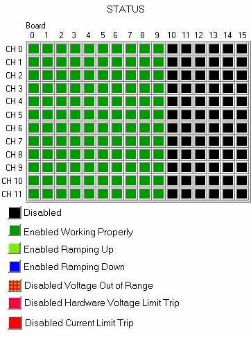
A. Status Display and Color Codes.
- The Status Display mocks the back of the mainframe as each
column is a board and each row is a channel.
- Color Codes.
- Black = Disabled.
- Green = Enabled and working properly.
- Orange = Disabled Measured Voltage out of ±
5V range from Requested Voltage.
- Yellow = Ramping Up to next absolute value.
- Blue = Ramping Down to next absolute value.
- Pink = Disabled Hardware Voltage Limit Trip.
- Red = Disabled Current Limit Trip.
B. Warning Alarm, Warning Alarm Switch, and Causes for Alarm.
- The alarm is a flashing button displayed in a separate window
with a constant beep.
- To turn off alarm press the button.
- Causes for Alarm.
- Hardware Voltage Limit Trip, which disables the channel,
is caused when the voltage exceeds this limit. The limit is set
on the back panel of each HV board. Also, when this trip occurs,
a red LED on the back panel of the board will be flashing.
- Current Trip occurs when current exceeds a software limit,
set at the start of the program. This limit can not be changed
while the program is running and is detector specific. When trip
occurs, the channel will be disabled.
- Out of Range Trip occurs when the measured voltage is ± 5V greater then the requested
voltage. This limit can not be set during the running of the
program. The channel is disabled when trip occurs.


IV. Template File, Latest Settings
File, and Writing to Database.
A. Template File.
- The format of the template file is as such.
Date: 11/22/99 4:15:06
Channel Req V Enabled
0       755      1
0.1     754      1
0.2     792      1
0.3     793      1
And so on.
For Enable: 1 is enabled and 0 is disabled.
- It is not advisable
to make and/or load a template file with out first discussing with all people with detectors hooked
up to the mainframe.
- It is advisable to use a proper name for
each template for easy access in the future.
B. Latest File
- HV_latest is the name of the file with the most recent settings.
- This file is rewritten during the initial start up of the
program after the template file has been chosen.
- This file has the same format as any template file.
- The latest template file is updated after each settings change
and after a new template is loaded into the mainframe.
C. Database
- The mainframe is read out every five minutes. The program
evaluates whether the current data is in agreement with the last
set data. If not, then the program will write the information
from that channel and only that channel to the database. If so,
then the program writes nothing.
- The second time the program writes to the database is every
six hours from the start of the program.
V. Stopping HV Mainframe Slow
Controls.
1. Click the Press to Stop Monitoring Mainframe
button.
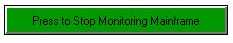
2. The program will cycle through one more read out from the
mainframe, which might take up to ten minutes.
3. Then, the program will write all values and settings to
the database and will update latest setting file one last time.