Experiment En-12
LCR Series Circuit
Description:
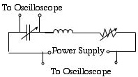
An inductor, a variable resistor, and a variable capacitor are connected in series
with a variable voltage supply. An oscilloscope is connected so that it can read
both the voltage drop across the capacitor and the voltage of the power source.
Experimental
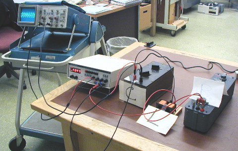
setup. Capacitor is marked "C," resistor is marked "R, and the
inductor is marked"L". The oscilloscope, showing a waveform produced
by the circuit, is in the upper left. The box between the circuit main and the
oscilloscope houses the transformers.
Schematic
for experimental setup.
Materials: wire,
oscilloscope, probes, variable capacitors, variable resistor, inductor
Back
to Site Menu
This page was last updated on
Friday August 15, 2008 8:37 PM


