NOTE
This manual describes the laboratory experiment used during the 1996 - 1997 academic year. Significant changes have been made since then, and the manual used during the current academic year is in NOT available yet on the WEB. Hardcopies can be purchased at the bookstore.
To verify the thin lens equation for both a biconvex lens and a concave mirror, and to construct simple optical devices using various combinations of lenses.
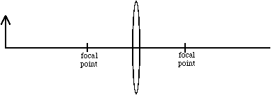
Various types of images are produced by lenses and mirrors, depending on the position of the object relative to the lens (mirror) and its focal point. In the following discussions, we use the attributes real or virtual, erect or inverted, and reduced or magnified to describe these images. The fundamental distinction between real and virtual images is that light rays converge to form a real image, while light rays diverge from a virtual image; real images may be projected onto a screen while virtual images must be viewed through a lens system such as the eye.
In this experiment, we use a simple "optical bench," a track upon which various combinations of objects and lenses (or mirrors) can be mounted. The separation of lens (or mirror) and object, denoted by u , and lens (or mirror) and image, denoted by v , can be measured by noting the relative position of each on the optical bench. If the focal length of a lens (mirror) is f, we may use the optical bench to check if the thin lens equation
1/u + 1/v = 1/f (12.1)
is satisfied for a given u and v. The bench will also be used to construct a compound microscope and two types of telescopes: astronomical and terrestrial.
The prelab homework must be done at home and handed to the lab TA before you start the lab. Read the instructions for this lab.
Questions


For this part, use the large bi-convex lens, an "object" (lamp), and an imaging screen. See Figure 12.1 for set up.

Figure 12.1
Assuming the thin lens equation (12.1) is satisfied, we may use the optical bench to measure u and v for several images in order to obtain a value for the focal length of the biconvex lens. The sign convention for equation (12.1) is that v is taken to be positive to the right of the lens and negative to the left.
Procedure
For this part use the concave mirror, the lamp, and the imaging screen. The thin lens equation is still obeyed, only u and v are defined as in figure 12.2, where v is taken to be negative behind the mirror.
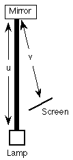
Figure 12.2
Procedure

Figure 12.3
The compound microscope uses two lenses. The one closest to the object is called the objective lens; the one closest to the observer is called the eyepiece.
The objective lens has a small focal length, possibly only a few millimeters. The object is placed slightly beyond the focal point of the objective in such a location as to form an enlarged real image inside the focal point of the eyepiece.
The eyepiece is then usually adjusted to form an enlarged virtual image about 25 cm from the viewer, as 25 cm is the standard value for the "near point" of the eye, or the closest point upon which the eye can focus. By having the image at the near point, its apparent size is maximized. The total magnification M of the microscope is the product of the lateral magnifications of the objective lens m1 and of the eyepiece m2 (i.e., |M| < 1 ==> image reduction, if M is positive the image is erect, and if M is negative the image is inverted.),
M = m1 m2. (12.2)
If the eyepiece forms a virtual image 25 cm behind the eyepiece, the image distance v is equal to -25 cm. We then may use the thin lens equation to write the magnification as
![]() , (12.3)
, (12.3)
where fe = 20cm is the focal length of the eyepiece.
We will use the above equation for m2 along with a measured value for m1, to investigate the total magnification M of the microscope.
Procedure
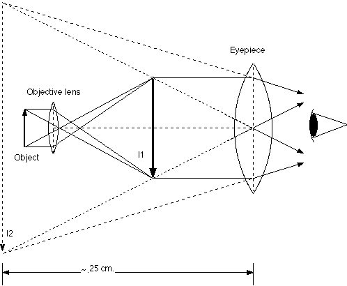
Figure 12.3
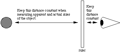
Figure 12.4
A. The Astronomical Refracting Telescope
For an astronomical telescope, the objective lens is always a lens with a long focal length. The objective lens produces a real image at its focal point. This image is magnified with the eyepiece. In this case, the eyepiece is usually adjusted so that the virtual image is at infinity, in this case a piece of paper across the room, but it may be adjusted to be closer.
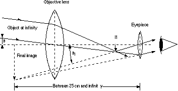
Figure12.5
Because theta and theta1 are small, they can be approximated as tan(theta) and tan(theta1), respectively. If h is the height of the real image I1 formed by the objective lens, then
![]() , (12.3)
, (12.3)
![]() , (12.4)
, (12.4)
and so,
![]() ,
,
where fo and fe are the focal lengths of the objective and eyepiece lenses, respectively. In addition, fo is the distance from the objective lens to I1 (because the image is at infinity) and fe is the distance from the eyepiece to I1 if the eyepiece is adjusted to give an image at infinity. The angular magnification then is,
 (12.5)
![]() . (12.6)
. (12.6)
Procedure for Astronomical Telescope
B. The Terrestrial Telescope (i.e. Opera Glass)
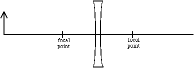
As in the astronomical telescope, the terrestrial telescope utilizes a long focal length lens and a short focal length eyepiece to produce a magnified image of a distant object. The magnification is again given by M = fo/fe. However, the eyepiece is a "meniscus" or concave lens rather than a convex lens, and things are somewhat different for this kind of telescope.
Procedure
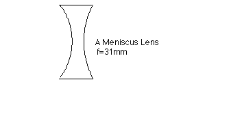
Figure 12.7
1/u + 1/v = 1/f (12.1)
The inverted real image
Here is a quick, easy, and perhaps perplexing demonstration you can do at home. There is no doubt that images in the eye are inverted, for this is the result of the crossing of light rays in the optical system of the eye. Why, if the images are upside-down, do we see things the right side up? It is quite possible to read plain print upside-down, and children just beginning to read sometimes choose to do so. A constellation of stars visible in both the northern and southern hemispheres is upside-down in one and not in the other, yet neither observer thinks of himself as anything but the right side up! Just as we "see" the normal, inverted image the right side up, if we produce an image right side up we may expect to "see" it inverted.
Make a pinhole (with a straight pin) in a piece of a file card. Hold the card about seven inches in front of one eye and look at the sky, the ceiling, or a blank wall. Then hold the pin vertically with its head uppermost between the card and your eye. The pinhead is too near to be focused in the ordinary way by the eye, but the rays of light from the hole cause it to cast a shadow on the retina. This shadow is right side up, and so the pinhead is seen upside-down in the hole. If there are several closely spaced holes there will be several shadows, and an inverted pinhead will appear in each hole!
If you have the time, study the inversion of your own image in a mirror. Why does the left side of your head appear on the right, and the right on the left in the image? Try tipping your head to one side and looking in the mirror. Why does your chin not replace your forehead and vice versa in the image? Is the inversion of the images that we see in a mirror merely a fallacy of our own perception? Can you sketch the paths of rays of light into your eye from the parts of your head you observe in a mirror?