NOTE
This manual describes the laboratory experiment used during the 1996 - 1997 academic year. Significant changes have been made since then, and the manual used during the current academic year is in NOT available yet on the WEB. Hardcopies can be purchased at the bookstore.
To observe interference patterns, and calculate the wavelength of a helium-neon laser and microwave radiation..
The prelab homework must be done at home and handed to the lab TA before you start the lab. Read the instructions for this lab.
The prevailing view of the nature of light has changed several
times in the past three centuries. Newton described light as a
stream of particles, partly because of its property of straight
line travel. In the 19th century, the notion that light
consists of waves came into acceptance. In this century it has
been shown that light behaves or more generally any part of the
electromagnetic spectrum with both particle-like and wave-like
properties. One method of observing this wave nature characteristic
is through the interference and diffraction of electromagnetic
radiation.
These experiments utilize a helium-neon laser of low power
( ![]() ). The beam of radiation is monochromatic (of a
single wavelength), coherent (in exactly the same phase-step),
and parallel.
). The beam of radiation is monochromatic (of a
single wavelength), coherent (in exactly the same phase-step),
and parallel.
CAUTION: Do not look directly into an undispersed laser beam or allow it to fall on your eyes.
For this part you will use the laser, the "multiple slit" slide, a screen, and a ruler to determine the wavelength of the laser radiation.
Turn the screw in only one direction to avoid `backlash' errors. Your lab assistant will help you. [This measurement does not need to be made first. Since there is only one microscope, you may want to wait a while to avoid the queue.]

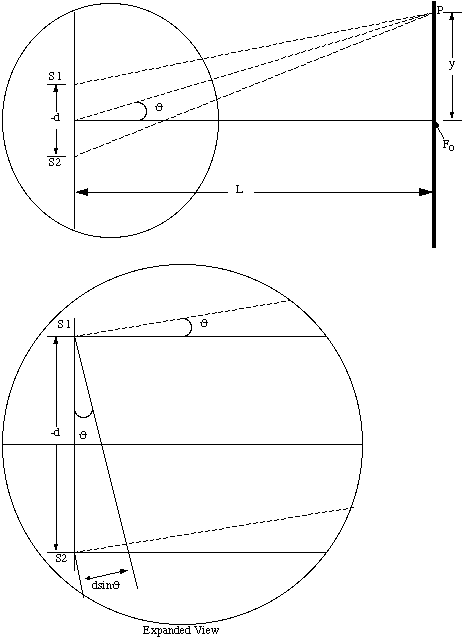
Figure 13.1
![]() (13.1)
(13.1)
Assuming that ![]() . This is shown in
Figure 13.2.
. This is shown in
Figure 13.2.
If you have a hypothesis to explain the screen interference pattern, check it with appropriate combinations of multiple slit slides.
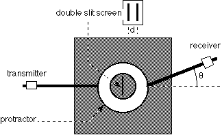
For this part, we demonstrate the wave nature of a different part of the electromagnetic spectrum. In the next room, use the microwave transmitter and receiver apparatus to determine the wavelength of microwave radiation. As in the optical counterpart, interference fringes will be produced by the double slit. Here, however, the separation of the fringes will be measured as an angle, not a displacement. The receiver has a meter used to measure the intensity of the radiation received.

Figure 13.2
![]() (13.2)
(13.2)
where ![]() is the wavelength and m
is an integer.
is the wavelength and m
is an integer.
From the graph, estimate the angular separation between two
adjacent fringes. Record this value. Using the measured value
of d, calculate the wavelength ![]() .
.

Figure 13.3
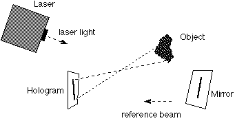
One of the most promising applications of continuous laser light is its ability to make three dimensional photographs called holograms. A hologram is made by exposing photographic film to a scene which is wholly illuminated with laser light. The film is simultaneously exposed to a reference beam that comes directly from the same laser. As the light from the laser and the scene falls upon the film, an interference pattern is recorded. The film is then developed to give a negative, which is the hologram. See Figure 13.4.
As you look at the hologram itself, the light and dark streaks and smudges you can see are not the places where the "information" is recorded. To see the interference pattern one needs to look at the hologram through a high magnification microscope. (The light and dark streaks and smudges are just that --streaks and smudges.)
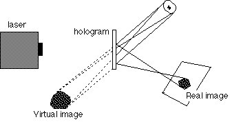
To view the scene, shine a light of the same wavelength on the hologram and look through it. In fact, two images are produced. One of them is virtual and behind the hologram, and the other is real and in front of the hologram.
It is relatively easy to see the virtual image. Look through the hologram from the position indicated on the desk. You should be able to see a three dimensional scene which was recorded on the hologram. If you move your head from side to side and up and down, you should be able to see the objects from different perspectives, just as you would if there were an actual group of real objects in front of you.

Figure 13.4
Make a hole about 1cm in diameter in the center of a sheet of note paper and move this over the face of the hologram while looking through it at the 3-dimensional scene. Notice that any portion of the hologram contains complete information for viewing the entire scene. However, there are some differences in the quality of the scene as you view through various portions of the hologram.

Figure 13.5
It is not very easy to see the real image which is projected in front of the hologram. Try to see the real image by looking from the position indicated. If you move your head from side to side and up and down you may possibly be able to tell that something is there, although the images will be confused. Try and determine whether the real image is inverted or erect, magnified or reduced.