 (Kinetic Energy)
To experimentally verify the laws of conservation of momentum and energy.
The laws of conservation of energy and momentum are among the most important and useful principles in physics. Conservation of momentum states that if a system of bodies has no net external forces acting on it, the total momentum is the same at all times (it is conserved). In addition, if all the forces, whether external or internal, can be given a potential, then the total energy is also a constant; this is the law of conservation of energy.
Despite their fundamental nature, the conservation laws are often difficult to observe in ordinary experience, primarily because of the presence of friction. Friction between moving bodies and their surroundings means there is an external force acting on them, so that conservation of momentum is not applicable. In addition, a potential energy cannot be defined for the force of friction, so energy is not conserved when friction is present. To observe the conservation laws, then, friction must be eliminated as much as possible.
This lab will primarily deal with the conservation laws as applied to collisions between material objects. Such collisions may be divided into two classes, depending on whether kinetic energy is conserved. If the only forces between two particles occur when they are in contact, then the kinetic energy at any time before and after a collision (when there are no net forces) must be the same. Solid bodies, however, are not particles, but have structure. If a collision between objects leaves their structure unchanged, then they may safely be treated as particles. This is known as an elastic collision, and in this case kinetic energy will be conserved. If this is not the case -- for example, if large numbers of atoms are rearranged or set in motion -- energy may flow into the structure of a body in ways that do not contribute to its overall motion. When this happens the collision is said to be inelastic and the kinetic energy of the bodies will not be conserved. Note that in the absence of friction or other external forces, momentum will be conserved for both type of collisions.
In one dimension, the conditions for before and after an elastic collision between two bodies (masses m1 and m2, initial velocities v1i and v2i, and final velocities v1f and v2f) is given mathematically as
 (Kinetic Energy)
 .
(Momentum)
For an inelastic collision, only the momentum equation is valid.
The prelab homework must be done at home and handed to the lab TA before you start the lab. Read the instructions for this lab.
For two objects in a one-dimensional collision, use the appropriate conservation laws to answer the following questions:

 .
.
Experiments
Part A: Air Track
An air track is a linear air bearing on which test gliders ride on a thin
cushion of compressed air which greatly reduces the effects of friction. A
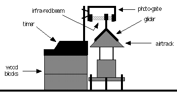
cross-section is shown in Figure 3.1. You will be able to measure the average
velocity of a glider by means of the photo-gate timer shown. This is an
electronic timer controlled by the interruption of an (invisible) infra-red
light beam when the glider passes through the gate. If an object of length
L interrupts the beam for a time interval
 while passing through the gate then,
 , (3.1)
is the average velocity of the object during that time. This is the basic type of measurement you will make in this experiment. By measuring the velocity of the gliders (and weighing them) you will determine their energy and momentum before and after various collisions and test the conservation laws.
Operation of the Timers
There are two different models of timers, and each air track should have one of each. Both models have an "off" switch, reset button and display, while one has an additional memory switch and red LED. To use a timer, switch from off to air track or gate position, depending on the model. (There are additional positions which are not used in this lab.)
If you pass your hand through the gate, for instance, it will count the time during which the beam is broken. The display units are in milliseconds. On the model with the memory feature, the display shows only the duration of the first interruption after the last reset. The duration of successive interruptions will be added to it in the memory. To display this number, flip the memory switch to read. On the model without a memory, the accumulated time of all the interruptions is shown directly on the display.

Figure 3.1

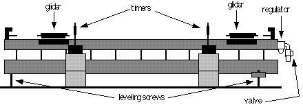
Figure 3.2
Operation of the Air Track
Compressed air is supplied to the air track through a regulator at one end. It can be turned on with the valve just below the regulator. There is a built-in scale on the track for making position and distance measurements. Please do not mark the air track.
The gliders have a spring bumper at each end, one of which is covered with a strip of Velcro. The uncovered bumpers can be used to generate elastic collisions, while the Velcro covered bumpers will generate inelastic collisions. Velcro comes in two varieties, small hooks and fibrous loops, so that when two pieces of opposite type come in contact they stick together. If the gliders do not stick together well, you may need to "roughen" the Velcro by repeatedly pushing the strips together and pulling them apart.
Inspect any glider before placing it on the track (look at and feel the bearing surface) to make sure that there are no irregularities, nicks or dings that might scratch the track and interfere with your measurements. The gliders are easily ruined if the bearing surface is marred, so be careful not to drop the gliders. Also, do not slide the gliders along the track when the air is turned off.
Procedure for Part A
You will need three gliders, two of the same mass but with opposite type of Velcro (ten such pairs are labeled), and one of a different size. You must distinguish between the different gliders and record the glider used for each measurement. You must also distinguish directions on the air track (calling a specific direction positive) for velocities.
Note, the gliders will not stick together if the speed is too great. Once together, there is only a small gap between the gliders, so use a timer with memory to measure this velocity. The display time will stop accumulating after the first glider has passed.
Data Analysis for Part A
 ,
(3.2)
where ti and tf are the earlier and later time intervals, respectively. Calculate the error in this ratio that could be due to timing errors (making reasonable estimates of the errors due to the timers). Is Newton's First Law verified?
The presence of any external forces, such as friction or gravity, will create a systematic error in all further measurements. To get a rough estimate of the effect this will have, calculate the average fraction of the initial energy and momentum lost for your the data from Part A2. Again, the masses and lengths factor out, leaving
 (3.3)
(3.3)
 .
(3.4)
You may average the fraction tf / ti (you already calculated these numbers) first; it is not correct to average tf and ti independently.
 , (3.5)
 .
(3.6)
Velocity and momentum have directions, and so give them signs in your calculations. The results are the fraction of the initial momentum and energy that are conserved. To compensate for direction dependent effects, calculate the average value of these fractions for each pair of trials in which the initial motion was in opposite directions.
In this experiment the velocity of a projectile as it leaves a spring gun will be measured using two methods. First the conservation laws will be used in a somewhat subtle way to determine the velocity. For comparison, it will also be measured using projectile motion.
Part B1 Measuring velocity with a Ballistic
Pendulum
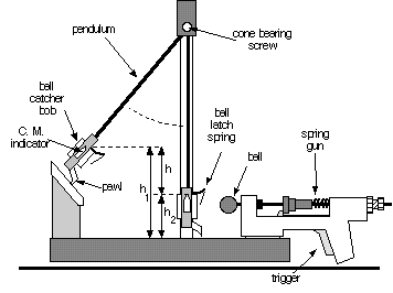
A ball is shot by the spring gun into a catcher arranged to swing as a pendulum. When the ball is caught, the combination of the ball and catcher become the bob of the pendulum. Although the collision between ball and catcher is inelastic and energy is not conserved, momentum is. With the catcher at rest, the initial momentum of the system is provided by the ball, shot with velocity vb. Immediately after the ball is caught, the momentum is that due to motion of the center of mass of the pendulum assembled from the catcher and ball, having velocity vp . Conservation of momentum requires these be the same,
 , (3.7)
where m and M are the masses of the ball and pendulum respectively.
After the ball is caught, the energy of the combined ball and catcher system is conserved. Initially the center of mass is at a height h1, with velocity vp. As it moves upwards against the force of gravity, the kinetic energy is converted into potential energy. A pawl mechanism latches it at its highest point, h2, where all the initial kinetic energy of the pendulum has been used to produce a change in the potential energy,
 ,
(3.8)
which can be determined by measuring the increase in height h = h1 - h2 of the center of mass of the assembly. The value of the initial velocity of the ball is,
 .
(3.9)

Figure 3.3
Procedure for Part B1
Be sure your apparatus is firmly fastened down so it will not move during the experiment. Check to make sure the base is level and adjust if necessary. The ball mounts on the gun's push rod via a hole through its diameter. Make sure this fits smoothly on your apparatus. Make sure that the ball latch spring is aligned with the spring gun.

Figure 3.4
Part B2: Measuring velocity with projectile motion
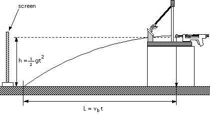
With the catcher removed from its path, the ball will fall freely after it leaves the gun. It will follow a parabolic arc until it hits the table top, traveling a horizontal distance L while falling a vertical distance h. The equations of projectile motion can be used to analyze the motion in theses directions, as shown in figure 3.5. Combining the two equations to eliminating time, the initial velocity of the ball is then
 . (3.10)

Figure 3.5
Procedure for Part B2
Make sure the apparatus is securely fastened and leveled on a block on the table. Latch the pendulum bob out of the way and practice firing the ball from the gun out over the table. Note where the ball lands. Be careful of wild shots.
 .
(3.11)